Introduction to Rigid-Flex PCBs and their Advantages
Rigid-flex PCBs are a unique combination of rigid and flexible printed circuit boards that offer numerous advantages over traditional Flexible PCBs in electronic projects. These hybrid boards consist of Rigid PCB sections connected by flexible PCB layers, allowing for a more compact, reliable, and versatile design solution. In this article, we will explore the various benefits of using rigid-flex PCBs and why they are often preferred over flexible PCBs in electronic projects.
What are Rigid-Flex PCBs?
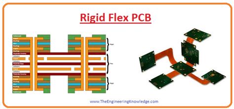
Rigid-flex PCBs are a type of printed circuit board that combines the stability and durability of rigid PCBs with the flexibility and adaptability of flexible PCBs. They are constructed by laminating together rigid PCB sections with flexible PCB Layers, creating a single, integrated board that can be bent, folded, or twisted to fit into tight spaces or conform to unique shapes.
Advantages of Rigid-Flex PCBs over Flexible PCBs
-
Enhanced Reliability: Rigid-flex PCBs offer improved reliability compared to flexible PCBs due to their robust construction and the presence of rigid sections that provide structural support. The rigid portions of the board protect the flexible layers from excessive bending or stretching, reducing the risk of damage and ensuring a longer lifespan for the electronic device.
-
Space Savings: One of the primary advantages of rigid-flex PCBs is their ability to save space in electronic projects. By combining rigid and flexible sections, designers can create more compact and efficient layouts that minimize the overall footprint of the device. This is particularly valuable in applications where space is limited, such as wearable electronics, medical devices, or aerospace systems.
-
Reduced Weight: Rigid-flex PCBs can help reduce the overall weight of an electronic device compared to using separate rigid and flexible PCBs. By integrating the two types of boards into a single unit, designers can eliminate the need for additional connectors, cables, and hardware, resulting in a lighter and more streamlined design.
-
Improved Signal Integrity: The seamless integration of rigid and flexible sections in a rigid-flex PCB helps maintain signal integrity throughout the board. The continuous copper traces that run through both the rigid and flexible layers minimize the risk of signal loss or interference, ensuring reliable data transmission and overall system performance.
-
Enhanced Durability: Rigid-flex PCBs are designed to withstand the stresses and strains of repeated bending and flexing, making them more durable than flexible PCBs alone. The rigid sections provide structural support and help distribute the mechanical stress evenly across the board, reducing the risk of damage due to fatigue or wear and tear.
Applications of Rigid-Flex PCBs
Rigid-flex PCBs find applications in a wide range of industries and electronic projects where space constraints, reliability, and flexibility are critical factors. Some common applications include:
-
Wearable Electronics: Rigid-flex PCBs are ideal for wearable devices such as smartwatches, fitness trackers, and medical monitoring systems. The flexible sections allow the board to conform to the shape of the human body, while the rigid sections provide structural support and house the necessary components.
-
Aerospace and Defense: In aerospace and defense applications, where weight and space are at a premium, rigid-flex PCBs offer a compact and lightweight solution. They can be designed to fit into tight spaces and withstand the harsh environmental conditions encountered in these industries.
-
Automotive Electronics: Rigid-flex PCBs are increasingly used in automotive electronics, such as infotainment systems, driver assistance features, and vehicle control modules. The ability to bend and fold the board allows for efficient packaging and routing of signals within the limited space available in modern vehicles.
-
Medical Devices: Medical devices often require a combination of reliability, flexibility, and compact design. Rigid-flex PCBs are well-suited for applications such as implantable devices, surgical instruments, and diagnostic equipment, where the board must conform to unique shapes and withstand repeated use.
-
Industrial Automation: In industrial automation systems, rigid-flex PCBs can be used to create compact and rugged control modules, sensors, and communication devices. The flexibility of the board allows for easy integration into tight spaces and the ability to withstand vibrations and harsh environmental conditions.

Design Considerations for Rigid-Flex PCBs
When designing rigid-flex PCBs, there are several key considerations to keep in mind to ensure optimal performance and reliability:
-
Bend Radius: The bend radius refers to the minimum radius at which the flexible sections of the board can be bent without causing damage. It is essential to design the board with the appropriate bend radius in mind, taking into account the thickness of the flexible layers and the number of copper traces running through them.
-
Layer Stackup: The layer stackup of a rigid-flex PCB is crucial for ensuring the board’s performance and reliability. Designers must carefully consider the number and placement of rigid and flexible layers, as well as the type and thickness of the dielectric materials used. Proper layer stackup design helps minimize signal interference, improves impedance control, and enhances the overall mechanical stability of the board.
-
Copper Thickness: The thickness of the copper traces in the flexible sections of the board should be carefully selected to ensure adequate flexibility and durability. Thinner copper traces are more flexible but may be prone to damage during repeated bending. Thicker traces offer better durability but may limit the board’s flexibility. Finding the right balance is essential for optimal performance.
-
Coverlay Selection: The coverlay is a protective layer that covers the flexible sections of the board, providing insulation and mechanical protection. Selecting the appropriate coverlay material and thickness is crucial for ensuring the board’s flexibility and durability. Common coverlay materials include polyimide, polyester, and solder mask.
-
Panelization: Panelization refers to the process of arranging multiple rigid-flex PCBs on a single panel for fabrication. Proper panelization is essential for ensuring efficient manufacturing and minimizing waste. Designers must consider factors such as the size and shape of the individual boards, the spacing between them, and the placement of tooling holes and fiducial marks.

Manufacturing Process for Rigid-Flex PCBs
The manufacturing process for rigid-flex PCBs is more complex than that of traditional rigid or flexible PCBs due to the combination of different materials and the need for precise alignment and lamination. The general steps involved in the manufacturing process are as follows:
-
Material Selection: The first step is to select the appropriate materials for the rigid and flexible sections of the board, including the base substrate, copper foil, dielectric materials, and coverlay.
-
Fabrication of Rigid and Flexible Layers: The rigid and flexible layers are fabricated separately using standard PCB manufacturing techniques such as etching, drilling, and plating.
-
Lamination: The rigid and flexible layers are then laminated together using high temperature and pressure to create a single, integrated board. Precise alignment is critical during this step to ensure proper connectivity between the layers.
-
Drilling and Plating: After lamination, the board undergoes drilling and plating to create the necessary vias and interconnects between the layers.
-
Coverlay Application: The flexible sections of the board are then covered with the selected coverlay material to provide insulation and mechanical protection.
-
Surface Finishing: Finally, the board undergoes surface finishing, such as solder mask application and silkscreen printing, to protect the copper traces and improve solderability.

Cost Considerations for Rigid-Flex PCBs
Rigid-flex PCBs are generally more expensive than traditional rigid or flexible PCBs due to the more complex manufacturing process and the use of specialized materials. However, the cost can be justified in many applications due to the numerous benefits they offer, such as space savings, improved reliability, and enhanced performance.
When evaluating the cost of rigid-flex PCBs, it is essential to consider the total cost of ownership (TCO) rather than just the initial fabrication cost. While rigid-flex PCBs may have a higher upfront cost, they can lead to significant savings in the long run by reducing the need for additional connectors, cables, and assembly steps. They can also help minimize the risk of failures and repairs, resulting in lower maintenance costs over the product’s lifetime.
Future Trends in Rigid-Flex PCB Technology
As electronic devices continue to become smaller, more complex, and more multifunctional, the demand for rigid-flex PCBs is expected to grow. Some of the key trends shaping the future of rigid-flex PCB technology include:
-
Miniaturization: The trend towards miniaturization is driving the development of even smaller and more compact rigid-flex PCBs. This involves the use of thinner materials, finer pitch components, and advanced manufacturing techniques such as high-density interconnect (HDI) and embedded component technology.
-
High-Speed Applications: Rigid-flex PCBs are increasingly being used in high-speed applications, such as 5G communication systems and high-performance computing. This requires the development of advanced materials and design techniques to ensure signal integrity and minimize losses at higher frequencies.
-
3D Printing: The use of 3D printing technology in PCB Fabrication is gaining traction, and this trend is expected to extend to rigid-flex PCBs as well. 3D printing offers the potential for faster prototyping, greater design flexibility, and the ability to create complex shapes and structures that are difficult to achieve with traditional manufacturing methods.
-
Sustainable Materials: There is a growing emphasis on the use of sustainable and eco-friendly materials in PCB manufacturing. This includes the development of halogen-free and recyclable materials for both rigid and flexible sections of the board, as well as the adoption of green manufacturing processes that minimize waste and environmental impact.
Frequently Asked Questions (FAQ)
-
Q: What is the difference between a rigid-flex PCB and a flexible PCB?
A: A rigid-flex PCB is a hybrid board that combines rigid PCB sections with flexible PCB layers, while a flexible PCB is entirely made of flexible materials. Rigid-flex PCBs offer the benefits of both rigidity and flexibility in a single integrated board, whereas flexible PCBs are designed for applications that require a high degree of flexibility and conformity. -
Q: Can rigid-flex PCBs be used in high-temperature applications?
A: Yes, rigid-flex PCBs can be designed to withstand high temperatures by using appropriate materials and manufacturing techniques. This includes the use of high-temperature substrates, dielectric materials, and solders that can withstand the required operating conditions. -
Q: How do I choose the right coverlay material for my rigid-flex PCB?
A: The choice of coverlay material depends on several factors, such as the required flexibility, durability, and environmental resistance. Common coverlay materials include polyimide, polyester, and solder mask. Polyimide is known for its high temperature resistance and durability, while polyester offers good flexibility and electrical properties. Solder mask is often used when the flexible sections require soldering or additional protection. -
Q: Are rigid-flex PCBs more difficult to assemble than traditional PCBs?
A: Assembling rigid-flex PCBs can be more challenging than traditional PCBs due to the presence of flexible sections and the need for special handling and fixturing. However, with proper planning and the use of appropriate assembly techniques, such as the use of stiffeners and support structures, the assembly process can be streamlined and optimized for reliability and efficiency. -
Q: How can I ensure the reliability of my rigid-flex PCB design?
A: To ensure the reliability of your rigid-flex PCB design, consider the following factors: - Use appropriate materials and layer stackup for your specific application requirements.
- Follow recommended design guidelines for bend radius, copper thickness, and coverlay selection.
- Perform thorough testing and validation, including mechanical stress testing and environmental testing.
- Work closely with your PCB manufacturer to ensure proper fabrication and assembly processes are followed.
- Consider using simulation tools and finite element analysis (FEA) to predict and optimize the board’s performance under various conditions.
Conclusion
Rigid-flex PCBs offer numerous advantages over traditional flexible PCBs in electronic projects, including enhanced reliability, space savings, reduced weight, improved signal integrity, and enhanced durability. These benefits make them an attractive choice for a wide range of applications, from wearable electronics and medical devices to aerospace systems and industrial automation.
When designing rigid-flex PCBs, it is essential to consider factors such as bend radius, layer stackup, copper thickness, coverlay selection, and panelization to ensure optimal performance and reliability. The manufacturing process for rigid-flex PCBs is more complex than that of traditional PCBs, involving precise alignment and lamination of the rigid and flexible layers.
Although rigid-flex PCBs may have a higher initial cost compared to flexible PCBs, the total cost of ownership can be lower due to the reduced need for additional components and the improved reliability and durability they offer.
As electronic devices continue to evolve and become more complex, the demand for rigid-flex PCBs is expected to grow. Future trends in rigid-flex PCB technology include further miniaturization, the use of advanced materials and manufacturing techniques for high-speed applications, the adoption of 3D printing for faster prototyping and greater design flexibility, and the increasing use of sustainable and eco-friendly materials.
By understanding the advantages, design considerations, and manufacturing processes involved in rigid-flex PCBs, engineers and designers can leverage this technology to create more compact, reliable, and high-performance electronic devices that meet the ever-growing demands of today’s market.
| Characteristic | Rigid-Flex PCB | Flexible PCB |
|---|---|---|
| Rigidity | Combines rigid and flexible sections | Entirely flexible |
| Reliability | Enhanced due to rigid sections and robust construction | Lower due to lack of structural support |
| Space Savings | Significant, due to compact and efficient layouts | Moderate, as they can conform to tight spaces |
| Weight | Reduced, as fewer connectors and cables are needed | Lightweight, but may require additional components |
| Signal Integrity | Improved, due to continuous copper traces and minimized signal loss | Prone to signal loss and interference |
| Durability | High, designed to withstand repeated bending and flexing | Lower, as they lack the support of rigid sections |
| Cost | Higher initial cost, but lower total cost of ownership | Lower initial cost, but may require more components and assembly steps |


Leave a Reply