Introduction to Countersinks and Counterbores in PCB Design
When designing a printed circuit board (PCB), it’s essential to consider the various components and their mounting requirements. Two common techniques used for accommodating screw heads or other fasteners on a PCB are countersinking and counterboring. While both methods create recesses in the PCB, they serve different purposes and have distinct characteristics.
In this article, we will explore the differences between countersinks and counterbores in PCB design, their applications, advantages, and disadvantages. We will also discuss the manufacturing processes involved and provide examples of when to use each technique.
Table of Contents
- What is a Countersink?
- Definition and Characteristics
- Applications and Benefits
-
Disadvantages and Limitations
-
What is a Counterbore?
- Definition and Characteristics
- Applications and Benefits
-
Disadvantages and Limitations
-
Countersink vs Counterbore: Key Differences
- Depth and Diameter
- Screw Head Accommodation
- Manufacturing Process
-
Design Considerations
-
Manufacturing Processes for Countersinks and Counterbores
- Drilling Techniques
- Depth Control
-
Surface Finishing
-
When to Use a Countersink or Counterbore in PCB Design
- Factors to Consider
-
Examples and Use Cases
-
Best Practices for Implementing Countersinks and Counterbores
- Design Guidelines
- Tolerances and Specifications
-
Quality Control Measures
-
Frequently Asked Questions (FAQ)
- What are the common drill bit sizes for countersinks and counterbores?
- Can countersinks and counterbores be used together on the same PCB?
- How do countersinks and counterbores affect the overall PCB Thickness?
- Are there any specific requirements for selecting screws for countersunk or counterbored holes?
-
How do countersinks and counterbores impact the assembly process?
-
Conclusion
- Recap of Key Points
- Future Trends and Innovations
1. What is a Countersink?
Definition and Characteristics
A countersink is a conical recess created in a PCB hole to accommodate the head of a flat-head screw or other fastener. The countersink allows the screw head to sit flush with the surface of the PCB, providing a smooth and level appearance. Countersinks are typically used when a low-profile or flush mounting is required, such as in applications where the PCB needs to be mounted close to another surface or component.
The primary characteristics of a countersink include:
- Conical shape with a specific angle (typically 82° or 90°)
- Depth that matches the height of the screw head
- Diameter that accommodates the screw head diameter
Applications and Benefits
Countersinks are commonly used in PCB design for various applications, such as:
- Mounting PCBs to enclosures or chassis
- Securing heat sinks or other components to the PCB
- Providing a flush surface for labeling or coating
- Improving the aesthetic appearance of the PCB
The benefits of using countersinks in PCB design include:
- Allows for flush mounting of screws or fasteners
- Provides a clean and professional appearance
- Reduces the overall height of the PCB Assembly
- Improves the stability and security of the mounted components
Disadvantages and Limitations
While countersinks offer several advantages, they also have some disadvantages and limitations:
- Limited depth due to the conical shape, which may not accommodate thick screw heads
- Reduced hole diameter at the surface, which can affect the PCB’s structural integrity
- Increased manufacturing complexity and cost compared to simple through-holes
- Potential for stress concentration around the countersink, especially in thinner PCBs

2. What is a Counterbore?
Definition and Characteristics
A counterbore is a cylindrical recess created in a PCB hole to accommodate the head of a socket head cap screw or other fastener with a cylindrical head. Unlike a countersink, a counterbore has a flat bottom and straight walls, allowing the screw head to sit below the surface of the PCB. Counterbores are typically used when a flush mounting is not required, but the screw head needs to be recessed for clearance or to prevent interference with other components.
The primary characteristics of a counterbore include:
- Cylindrical shape with straight walls
- Flat bottom that matches the height of the screw head
- Diameter that accommodates the screw head diameter
- Depth that allows the screw head to sit below the PCB surface
Applications and Benefits
Counterbores are commonly used in PCB design for various applications, such as:
- Mounting PCBs to standoffs or spacers
- Securing components with socket head cap screws
- Providing clearance for screw heads in multi-layer PCB assemblies
- Accommodating thicker screw heads or fasteners
The benefits of using counterbores in PCB design include:
- Allows for recessed mounting of screws or fasteners
- Provides clearance for thicker screw heads or components
- Maintains the full hole diameter through the PCB, improving structural integrity
- Simplifies the manufacturing process compared to countersinks
Disadvantages and Limitations
Counterbores also have some disadvantages and limitations:
- Increases the overall thickness of the PCB assembly due to the recessed screw head
- May require additional drilling operations, increasing manufacturing time and cost
- Can create air gaps or voids around the screw head, potentially affecting thermal or electrical performance
- May not provide a completely flush surface, which can be aesthetically undesirable in some applications

3. Countersink vs Counterbore: Key Differences
Depth and Diameter
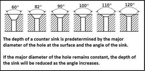
One of the primary differences between countersinks and counterbores is their depth and diameter. Countersinks have a conical shape that gradually decreases in diameter as the depth increases, while counterbores have a constant diameter throughout their depth. This means that countersinks are limited in their ability to accommodate thicker screw heads, while counterbores can be designed to accommodate screw heads of various heights.
Screw Head Accommodation
Countersinks are specifically designed for flat-head screws, which have a conical underside that matches the angle of the countersink. This allows the screw head to sit flush with the PCB surface. On the other hand, counterbores are designed for socket head cap screws or other fasteners with cylindrical heads, which sit below the PCB surface in the counterbore recess.
Manufacturing Process
The manufacturing process for creating countersinks and counterbores differs slightly. Countersinks are typically created using a special countersink drill bit that has a conical shape and a specific angle. The depth of the countersink is controlled by the depth stop on the drilling machine or by using a depth-controlled drilling process.
Counterbores, on the other hand, are created using a two-step drilling process. First, a standard drill bit is used to create the through-hole, and then a larger diameter drill bit is used to create the counterbore recess to a specific depth. This process requires more precise depth control and may take longer than creating a countersink.
Design Considerations
When deciding between a countersink and a counterbore, designers must consider several factors, such as:
- The type of screw or fastener being used (flat-head or socket head)
- The required flush mounting or clearance for components
- The thickness of the PCB and the depth of the recess
- The structural integrity of the PCB and the hole diameter
- The aesthetics and appearance of the final assembly
Designers should also consider the manufacturing capabilities and costs associated with creating countersinks or counterbores, as well as any specific requirements for the end application.

4. Manufacturing Processes for Countersinks and Counterbores
Drilling Techniques
Countersinks and counterbores are created using different drilling techniques. For countersinks, a specialized countersink drill bit is used, which has a conical shape and a specific angle (usually 82° or 90°). The drill bit is plunged into the PCB to create the conical recess, with the depth controlled by a depth stop or a depth-controlled drilling process.
Counterbores are created using a two-step drilling process. First, a standard drill bit is used to create the through-hole, and then a larger diameter drill bit is used to create the counterbore recess. The depth of the counterbore is controlled by a depth stop or a depth-controlled drilling process, ensuring that the recess is deep enough to accommodate the screw head.
Depth Control
Accurate depth control is crucial for both countersinks and counterbores to ensure that the screw head sits at the correct level and does not interfere with other components or surfaces. For countersinks, the depth is typically controlled by a depth stop on the drilling machine, which limits the plunge depth of the countersink drill bit.
For counterbores, depth control is achieved using a depth stop or a depth-controlled drilling process. The depth of the counterbore recess must be carefully calculated based on the height of the screw head and the thickness of the PCB to ensure a proper fit.
Surface Finishing
After drilling the countersinks or counterbores, the PCB may require additional surface finishing to ensure a smooth and clean appearance. This can include deburring, which removes any rough edges or burrs around the hole, and plating, which adds a layer of conductive material (such as copper, nickel, or gold) to the hole walls to improve electrical conductivity and protect against corrosion.
In some cases, the countersinks or counterbores may also be filled with a non-conductive material, such as epoxy or resin, to provide a completely flush surface and improve the structural integrity of the PCB.
5. When to Use a Countersink or Counterbore in PCB Design
Factors to Consider
When deciding whether to use a countersink or counterbore in a PCB design, designers must consider several factors, including:
- Screw type and head shape: Flat-head screws require countersinks, while socket head cap screws or other fasteners with cylindrical heads require counterbores.
- Flush mounting requirements: If a flush surface is desired for aesthetic or functional reasons, a countersink is typically the best choice.
- Component clearance: If there are components or other obstructions near the mounting hole, a counterbore may be necessary to provide adequate clearance for the screw head.
- PCB thickness and structural integrity: Countersinks remove more material from the PCB, which can reduce its structural integrity, particularly in thinner boards. Counterbores maintain the full hole diameter, providing better strength.
- Manufacturing capabilities and costs: The complexity and cost of creating countersinks or counterbores should be considered, as well as the available manufacturing equipment and expertise.
Examples and Use Cases
Here are some examples of when to use countersinks or counterbores in PCB design:
- Mounting a PCB to an enclosure: Use countersinks with flat-head screws for a flush and secure mounting.
- Attaching a heat sink to a PCB: Use counterbores with socket head cap screws to provide clearance for the screw heads and ensure good thermal contact.
- Securing a PCB to standoffs: Use counterbores to recess the screw heads and prevent interference with other components.
- Mounting a display module to a PCB: Use countersinks to achieve a flush and seamless appearance.
- Assembling multi-layer PCBs: Use counterbores to provide clearance for screw heads in the inner layers, preventing interference with other components or layers.
6. Best Practices for Implementing Countersinks and Counterbores
Design Guidelines
To ensure the proper implementation of countersinks and counterbores in PCB design, follow these guidelines:
- Specify the correct screw type and size: Ensure that the screw type (flat-head or socket head) and size are compatible with the countersink or counterbore dimensions.
- Define the required depth and diameter: Clearly specify the depth and diameter of the countersink or counterbore based on the screw head dimensions and PCB thickness.
- Consider the PCB material and thickness: Ensure that the PCB material and thickness can accommodate the countersink or counterbore without compromising structural integrity.
- Provide adequate Annular Ring: Maintain sufficient annular ring (copper pad) around the hole to ensure proper electrical connection and mechanical strength.
- Adhere to manufacturer’s recommendations: Follow the PCB manufacturer’s guidelines for minimum Hole Sizes, pad sizes, and drilling capabilities.
Tolerances and Specifications
When specifying countersinks and counterbores in PCB design, it’s essential to provide clear tolerances and specifications to ensure proper manufacturing and assembly. This includes:
- Hole diameter tolerance: Specify the acceptable range for the hole diameter, considering the screw size and PCB material.
- Countersink or counterbore depth tolerance: Define the acceptable range for the depth of the recess, ensuring compatibility with the screw head height.
- Surface finish requirements: Specify the required surface finish (such as plating or filling) for the countersink or counterbore, if applicable.
- Positional tolerance: Define the acceptable deviation from the specified hole position, considering the assembly requirements and component placement.
Quality Control Measures
To ensure the quality and consistency of countersinks and counterbores in PCB manufacturing, implement the following quality control measures:
- Visual inspection: Perform visual checks to verify the presence, position, and appearance of countersinks and counterbores.
- Depth measurement: Use depth gauges or optical measuring equipment to verify that the countersink or counterbore depth is within the specified tolerance.
- Hole size verification: Check the hole diameter using pin gauges or optical measuring equipment to ensure compatibility with the screw size.
- Cross-sectioning: Perform destructive testing on a sample of PCBs to verify the internal structure and dimensions of the countersinks or counterbores.
- Functional testing: Assemble the PCBs with the specified screws and fasteners to verify proper fit and functionality.
By implementing these best practices and quality control measures, designers and manufacturers can ensure the reliable and consistent implementation of countersinks and counterbores in PCB design and production.
7. Frequently Asked Questions (FAQ)
What are the common drill bit sizes for countersinks and counterbores?
The drill bit sizes for countersinks and counterbores depend on the specific screw sizes and PCB requirements. Common countersink drill bit sizes include:
– 82° countersink: #0, #1, #2, #3, #4, #5, #6, #8, #10
– 90° countersink: #2, #4, #6, #8, #10
Common counterbore drill bit sizes are:
– M2, M2.5, M3, M4, M5, M6 (metric)
– #4, #6, #8, #10, 1/4″, 5/16″ (imperial)
Can countersinks and counterbores be used together on the same PCB?
Yes, countersinks and counterbores can be used together on the same PCB, depending on the specific mounting requirements and component placement. For example, a PCB may use countersinks for mounting to an enclosure and counterbores for securing heat sinks or other components.
How do countersinks and counterbores affect the overall PCB thickness?
Countersinks and counterbores both add to the overall thickness of the PCB assembly, as they create recesses for the screw heads. Countersinks typically have a shallower depth and may not significantly increase the PCB thickness, while counterbores can add more depth and may require a thicker PCB or spacers to accommodate the recessed screw heads.
Are there any specific requirements for selecting screws for countersunk or counterbored holes?
Yes, the screws selected for countersunk or counterbored holes must have compatible head shapes and sizes. For countersinks, use flat-head screws with a conical underside that matches the angle of the countersink (82° or 90°). For counterbores, use socket head cap screws or other fasteners with cylindrical heads that fit within the counterbore diameter and depth.
How do countersinks and counterbores impact the assembly process?
Countersinks and counterbores can impact the assembly process by requiring additional steps and considerations, such as:
– Ensuring proper alignment and orientation of the screws during assembly
– Verifying that the screw heads sit flush or at the correct depth within the recesses
– Applying appropriate torque to the screws to prevent damage to the PCB or components
– Considering the accessibility and clearance for tools used to fasten the screws
Designers and assemblers must account for these factors when planning the assembly process and selecting the appropriate tools and techniques for PCBs with countersinks or counterbores.
8. Conclusion
In conclusion, countersinks and counterbores are two essential techniques used in PCB design to accommodate screw heads and fasteners. While both methods create recesses in the PCB, they have distinct characteristics, applications, and manufacturing processes.
Countersinks are conical recesses that allow flat-head screws to sit flush with the PCB surface, providing a smooth and low-profile appearance. They are commonly used for mounting PCBs to enclosures or achieving a seamless


Leave a Reply