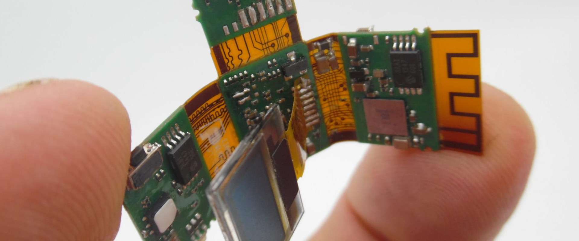
Flexible printed circuit boards (flex PCBs) have become an integral part of modern electronics due to their ability to bend and flex to fit into tight spaces. Determining the right thickness for your flex PCB design is an important consideration impacting the durability, reliability, and manufacturability of your product. In this article, we’ll look at the standard thickness ranges for flex PCBs and the factors that influence thickness selection.
Overview of Flex PCB Thicknesses
The thickness of a flex PCB refers to the height of the circuitry and dielectric layers that make up the board. While rigid PCBs have a standard 1.6mm thickness, flex PCBs can range dramatically in thickness from 25 μm to over 500 μm.
Here are some typical flex PCB thickness ranges:
- Ultra-thin: 25-50 μm
- Thin: 50-100 μm
- Standard: 100-150 μm
- Thick: 150-200 μm
Flex PCBs under 100 μm are considered ultra-thin or thin, while thicknesses above 100 μm are in the standard to thick range. The most common standard thickness for single-layer flex PCBs falls between 100-120 μm.
Factors that Determine Flex PCB Thickness
Several factors come into play when determining the appropriate thickness for your flex PCB design:
Number of Layers
The number of copper layers in the flex PCB impacts its overall thickness. More layers means more copper and dielectric material, increasing the total thickness. Single layer flex PCBs can be very thin, while multilayer designs tend to be thicker.
Conductor Thickness
The thickness of the copper conductors, or traces, also affects the overall flex PCB thickness. Common copper weights for flex PCBs range from 1⁄2 oz (18 μm) to 2 oz (70 μm) per square foot. Heavier copper provides better current carrying capacity.
Dielectric Material
The thickness of the insulating dielectric layer between copper layers contributes to the total PCB thickness. Common dielectrics like polyimide and PEN come in different thickness options. Thicker dielectrics provide better insulation and durability.
Stiffeners/Shielding
Some flex PCBs incorporate stiffeners or shielding layers to provide rigidity or protect from EMI/RFI interference. These additional layers will increase the total thickness. Stiffeners can add 50-100 μm while shielding can add 10-50 μm.
Coverlay/Mask
The solder mask coating on the outer flex PCB layers provides insulation and protection, adding 10-30 μm of thickness per side. Thicker coverlay offers robust protection.
Why Flex PCB Thickness Matters
The thickness of a flex PCB design impacts a number of important characteristics:
Flexibility
Thinner flex PCBs can bend into tighter radii than thicker boards. Ultra-thin boards under 50 μm can fold tightly like paper. Applications with dynamic flexing require thin, flexible circuit boards.
Durability
Thicker flex PCBs are inherently more durable and resistant to repeated bending. The thicker copper and dielectrics are less prone to cracking. Durability is critical for dynamic and high-stress applications.
Manufacturability
Thinner flex PCBs can be challenging to manufacture and handle without damage. Thicker boards over 150 μm are easier to fabricate and assemble. Extremely thin boards may not be suitable for some manufacturing processes.
Reliability
Adequate conductor and dielectric thickness ensures good insulation resistance and prevents electrical shorts. Thicker copper carries more current. Thinner boards are more prone to failures under shock, vibration, and extreme bending.
Weight and Space
Thinner flex PCBs take up less space and weigh less than thicker boards. This is desirable in ultra-compact and portable electronics. But they provide less mechanical support on their own.
Cost
In general, thinner flex PCBs require more careful handling during fabrication and assembly, driving up costs. Very thick boards with more layers and materials are also more expensive. Finding the optimum thickness balance is key.
Choosing the Right Flex PCB Thickness
Here are some best practices to determine the most appropriate thickness for your flex PCB design:
- Consider minimum bend radius – thinner for tighter folds
- Account for number of layers and copper weights
- Evaluate dielectric thickness needed for insulation and durability
- Analyze mechanical stress and vibration levels
- Plan for stiffeners and shielding if needed
- Review manufacturing capabilities on thickness limits
- Prototype multiple thicknesses for performance testing
- Partner with your flex PCB manufacturer early in the design process
While there are general guidelines on standard flex PCB thicknesses, the optimum thickness is driven by the specific requirements of each design. Partnering with an experienced flex PCB manufacturer will help determine the best thickness to meet your product’s functionality, reliability and manufacturing needs.
Common Questions About Flex PCB Thickness
Here are some frequently asked questions about selecting the right thickness for flex PCB designs:
What is the minimum bend radius for various flex PCB thicknesses?
- Ultrathin (< 50μm): 0.1mm
- Thin (50-100μm): 0.15mm
- Standard (100-120μm): 0.2mm
- Thick (>120μm): 0.25mm+
Thinner flex PCBs can bend to tighter radii before risking damage.
How do you calculate the thickness of a multilayer flex PCB?
Total thickness of a multilayer flex PCB is:
(2 * Coverlay thickness) + (Number of layers * Copper thickness) + ((Number of layers – 1) * Dielectric thickness)
So a 4-layer board with 25 μm coverlay, 18 μm copper, and 25 μm dielectric would be:
(2 * 25 μm) + (4 * 18 μm ) + (3 * 25 μm) = 186 μm
What is a typical thickness for a rigid-flex PCB?
Rigid-flex PCBs combine rigid boards and flex circuits. The rigid sections are usually standard 1.6mm thickness while the flex sections follow typical flex PCB guidelines. The rigid regions provide structural support while the thin flex areas allow dynamic bending.
Can you make a flex PCB too thin?
Yes, extremely thin flex PCBs below 25 microns are often too delicate for manufacturing and regular handling. They lose mechanical strength and are prone to cracking. Careful prototyping is needed to determine the minimum functional thickness.
What is the thinnest commercially available flex PCB?
Some manufacturers can produce single-layer flex PCBs as thin as 12 microns, though 25 microns is more common. Polyimide film can be thinner than 12 microns but requires special handling. The thinnest standard thickness is around 25 microns.
Conclusion
Determining the optimal flex PCB thickness requires balancing flexibility, durability, manufacturability, and cost. While thin boards provide tight bending radii, standard 100-150 μm thickness offers a robust design. Work closely with your flex PCB supplier to select the right number of layers, copper weights, dielectrics, and other features to meet the specific mechanical and electrical needs of your flex circuit design. With the right thickness you’ll end up with a high-performing and reliable flex PCB solution.


Leave a Reply