Introduction
A rigid flex rigid printed circuit board (PCB) is a type of circuit board that combines rigid and flexible circuit boards into a single structure. As the name suggests, rigid flex rigid PCBs provide the benefits of both rigid boards and flexible circuits. They allow complex interconnections between components while still providing rigidity and mechanical stability where needed. In recent years, rigid flex rigid PCBs have become increasingly popular due to their many advantages in a wide range of electronics applications.
What is a Rigid Flex Rigid PCB?
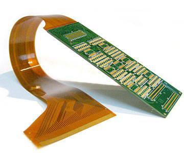
A rigid flex rigid PCB consists of rigid sections interconnected by flexible sections. The rigid sections provide mechanical support and stability, while the flexible sections allow dynamic flexing and motion. Rigid flex PCBs typically have multiple layers of copper traces separated by dielectric material. The materials and manufacturing processes used allow some areas of the PCB to remain rigid while other parts flex.
The rigid sections of the PCB are often made of standard FR-4 glass epoxy. The flexible areas can be made from polyimide or other flexible polymer materials. The layers are bonded together using adhesives suited for flexing applications.
Benefits of Rigid Flex Rigid PCBs
There are several key benefits that make rigid flex rigid PCBs advantageous compared to rigid PCBs or flex circuits alone:
Dynamic Flexing and Motion
The flexible sections of rigid flex PCBs allow dynamic flexing, bending, twisting or other types of mechanical motion. This allows the PCB to move, vibrate or adapt to physical changes without compromising integrity. The rigid sections provide stability and mounting where needed.
Space and Weight Savings
By combining rigid and flex materials in one PCB, rigid flex technology allows for significant space and weight savings versus utilizing separate rigid and flex boards. This is especially helpful in small, high-density devices.
Reliability
Rigid flex PCBs can offer greater reliability than assemblies using connectors between separate rigid and flex PCBs. Eliminating connectors removes a common point of failure.
Improved Signal Speed & Integrity
The continuous electrical paths along the length of a rigid flex PCB provide excellent signal speed and signal integrity. The elimination of connectors reduces impedance mismatches and discontinuities.
Design Flexibility
Rigid flex PCBs allow three-dimensional design flexibility not possible with rigid boards alone. Traces can fold around corners, components can be mounted on multiple sides, and boards can integrate specialized mechanical features.
Reduced System Complexity
By consolidating rigid and flex requirements into a single PCB, rigid flex technology simplifies system interconnections. This avoids the complexity of integrating separate rigid and flex boards in an assembly.
Lower Overall Costs
Despite higher per-board costs, rigid flex PCBs can significantly reduce total system cost by consolidating parts, simplifying assembly, increasing reliability, and miniaturizing design.
Rigid Flex PCB Construction and Materials
Rigid flex PCBs feature a complex construction with special materials to combine the necessary mechanical and electrical properties. Here are some key material considerations:
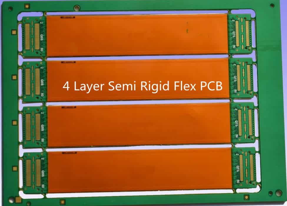
Layer Stackup
A rigid flex PCB will typically have a layer stackup comprising rigid FR-4 layers bonded to thinner flexible layers made from polyimide. Adhesives join the layers.
Dielectric Materials
The rigid sections use standard glass reinforced FR-4 material, while the flex sections use a flexible polymer like polyimide or PEEK. These materials provide the needed combination of flexibility, heat resistance, and electrical insulation.
Conductive Traces
The conductive traces are typically copper, etched and plated to form the required circuit layout. Special trace patterns or materials may be used in higher flex zones.
Coverlay/Masking
Top and bottom solder mask coverlays are used. These coatings protect traces and provide electrical insulation, abrasion resistance and moisture protection.
Bonding Adhesives
Acrylic, epoxy or urethane adhesives permanently bond the fabric and prepreg layers. These adhesives maintain adhesion during flexing.
Stiffeners
To selectively control flexibility, rigid stiffeners made from FR-4 or metal can be added to only stiffen certain areas.
Rigid Flex PCB Design Considerations
Rigid flex PCB design requires special considerations, both in terms of physical construction and circuit layout. Here are some key guidelines that designers should follow:
Layer Count
Use symmetric layer stacks with balanced material thicknesses to prevent warpage or twisting. Four to eight layers is typical.
High Trace Density
Rigid sections can accommodate higher trace densities and components vs. flexible areas. Position high density areas accordingly.
Flex Bend Areas
A minimum bend radius limits trace folding. Allow sufficient space for flex zones based on minimum bend requirements.
Stiffener Location
Strategically place stiffeners to control flexibility in certain areas while allowing flexing where needed.
Trace Layout
Use teardrop patterns or other techniques in flex areas to make traces more dynamic bending resistant. Avoid traces perpendicular to bends.
Components & Topology
Place heavy components in rigid zones. Use flexible components like chips-on-flex in flex zones. Optimize topology across rigid-flex junctions.
Testing
Test PCB dynamics early, including flexural life cycle testing. Ensure the PCB moves as intended without damage.
Following established design rules and working closely with your PCB manufacturer is key to a successful rigid flex PCB design.
Typical Applications of Rigid Flex PCBs
Some of the most common applications that benefit from using rigid flex PCB technology include:
Aerospace and Defense Electronics
Rigid flex PCBs are widely used in aerospace and defense applications where reliability, ruggedness, and vibration resistance are critical requirements. The dynamic flexing accommodates motion, vibration or shock.
Automotive Electronics
Automotive electronics like powertrain control units, engine control modules, ABS controllers, and body controllers rely on rigid flex PCBs. The boards provide reliability under hood while facilitating interconnections.
Medical Electronics
Medical devices like patient monitors, imaging equipment, and implantable devices use rigid flex PCBs to fit needed electronics into small, complex packages that undergo flexing and motion on and within the body.
Consumer Electronics
Cell phones, laptops, tablets, and wearables use rigid flex PCBs to achieve robust interconnections while providing flexibility for portability and range of motion required from daily use. The boards provide reliable performance despite frequent flexing.
Industrial Electronics
Industrial automation and robotics systems often require rigid board stability combined with dynamic flexing. Rigid flex PCBs serve these needs in motion control cards, servo controllers, sensors, and other devices.
High Speed Computing
High density rigid flex PCBs meet very precise electrical requirements in high speed computing applications. The technology provides excellent signal speed/integrity at the interconnect densities required.
The combination of rigidity, flexibility, tight interconnections, and reliability makes rigid flex PCBs the right choice for these and many other applications.
Rigid Flex PCB Manufacturing Considerations
Producing quality rigid flex PCBs requires specialized manufacturing and assembly processes tailored to the unique requirements and materials involved. Here are some key considerations:
Complex Layer Lamination
Rigid flex PCB fabrication involves precise alignment and high temperature, high pressure lamination of rigid and flex materials into a final circuit board.
Trace Routing & Flex Cuts
Traces are routed with precision along the interfaces between rigid and flex areas. Flex sections may require special trace geometries.
Surface Finishes
Immersion silver, immersion tin, OSP, and other finishes are used to protect and facilitate soldering and assembly of traces and component pads.
Coverlay Application
Applying protective solder mask requires tight process control to coat the mixture of plane, high density, and flexible board areas.
Via Formation
Laser, mechanical, or plasma processes selectively ablate conformal material to form vias connecting internal trace layers. Depth is carefully controlled.
Component Assembly
SMT and through hole assembly requires optimization to mount components on rigid, flex, and rigid-flex transition areas according to the design needs.
Each step in the PCB fabrication and assembly process requires specialized handling of rigid flex PCBs. Finding an expert rigid flex PCB manufacturing partner is key to producing a high quality finished board.
Rigid Flex PCB Testing
Verifying the performance and reliability of finished rigid flex PCBs and assemblies requires thorough testing tailored to the application requirements:
Design Validation
The initial PCB must be validated against electrical, mechanical, and functional design criteria through inspection and testing.
Continuity Testing
Flying probe or bed-of-nails testers electrically verify trace continuity, connectivity, and isolation across the entire rigid flex board.
Circuit Function Tests
Running dynamic function tests under simulated operating loads and motion ensures proper performance.
Flexure and Lifecycle Validation
The rigid flex PCB assembly must undergo extensive flexural life testing to verify durability and component adhesion over projected motion cycles.
Environmental Testing
Testing may include temperature cycling, shock/vibration, humidity exposure, thermal shock, altitude, etc. according to product specifications.
Quality Inspections
Inspections at multiple points in fabrication and assembly ensure adherence to process requirements and catch any defects.
Thorough testing provides confidence in initial design validation and long term reliability under field use conditions.
Conclusion
Rigid flex PCB technology offers unique advantages by combining rigid board stability with flexible circuit interconnections. Rigid flex PCBs are enabling electronics designers to achieve new levels of reliability, density, shape conformity, and design flexibility. With the right design expertise and manufacturing partner, rigid flex PCBs provide a robust interconnect solution for challenging modern electronic devices and systems.
Frequently Asked Questions (FAQ) About Rigid Flex Rigid PCBs
What are the main advantages of rigid flex PCBs?
The main advantages are dynamic flexing ability, space/weight savings, improved reliability, design flexibility, simplified interconnections, and potential lower system cost.
What types of electronics applications typically use rigid flex PCBs?
Aerospace, automotive, medical, consumer, and industrial electronics often rely on rigid flex PCB technology.
What are some key rigid flex PCB design considerations?
Important design considerations include layer stack ups, trace density, minimum bend radii, stiffener placement, trace layout techniques, component placement, and topology optimization.
What special steps are involved in rigid flex PCB manufacturing?
Key manufacturing processes like lamination, routing, finishing, lasering, and assembly require optimization for the combination of rigid and flex materials.
Why is testing important for finished rigid flex PCB assemblies?
Thorough testing verifies initial design, confirms reliability under dynamic operating conditions, and provides long term assurance of performance.


Leave a Reply