Introduction to Flex PCBs
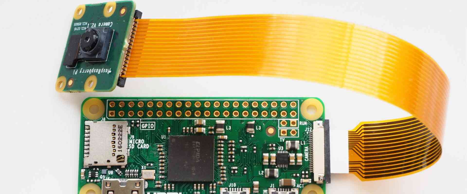
A flexible printed circuit board (FPCB), also known as a flex circuit, is a type of printed circuit board that is made with flexible substrate materials. This allows the board to bend and flex while still maintaining electrical connections. Flex PCBs are widely used in modern electronic devices like cellphones, wearables, medical devices, automotive electronics, and more. They allow circuitry to fit into tight spaces and move dynamically in ways that rigid PCBs cannot.
Some key properties and advantages of flex PCBs:
- Flexible – can bend, fold and flex repeatedly without damage
- Thin, lightweight – take up less space and weight
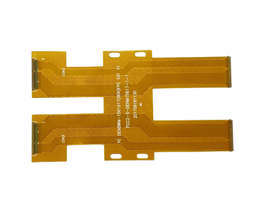
- Highly customizable – can be designed in nearly any 2D or 3D shape
- Durable under dynamic motion – ideal for moveable components
- Reliable connections – maintains conductivity even when flexed
- Easily embedded – can integrate with cables, displays, textiles, etc
In this guide, we will explore the assembly process for creating complete flex PCBs, from the initial design to final production.
Flex PCB Design Considerations
When designing a flex PCB, there are some important factors to consider:
Layer Stackup
The layer stackup defines the layer structure of the flex board. Typical stackups include:
- Single-sided: Circuitry on one side only
- Double-sided: Circuitry on both sides
- Multilayer: Multiple conductive layers laminated together
More layers allow higher circuit density, but add cost and thickness. One to two layer designs are common for simpler flex applications.
Conductor Traces
The conductive traces carry current through the circuit. Some key trace properties:
- Width/thickness – determines current capacity
- Pitch/spacing – distance between traces
- Flexibility – ability to flex without cracking
- Impedance – matches desired signal properties
Narrower traces allow higher density but lower current. Wider traces can carry more current.
Bend Radii
A key consideration is the minimum bend radius the PCB can tolerate. Tighter bends increase stresses and can damage traces. The minimum bend radius depends on:
- Substrate material
- Copper thickness
- Board thickness
- Desired flex life
Generally, thicker flex PCBs require a larger bend radius.
Substrate Material
Common substrate materials include:
- Polyimide – Excellent flex life, temperature resistance
- Polyester – More economical, lower flex life
- LCP – High frequency, complex 3D forms
Material choice affects cost, flexural properties, thermal behavior and chemical resistance.
Flex PCB Manufacturing Process
Professional flex PCB fabrication involves many steps to transform the initial design into a complete product.
Fabrication
The fabrication process is similar to rigid PCBs, but using flexible substrate materials. It includes:
- Imaging – Photomask creation
- Lamination – Layer stacking with adhesive
- Etching – Chemically removing copper
- Drilling – Creating thru-holes for vias
- Plating – Electroplating exposed pads/holes
- Solder mask – Protective coating
- Silkscreening – Component legends
Automated fabrication allows high volume at low cost.
Assembly
After fabrication, assembly adds components to create a functional PCB:
- SMT – Surface mount device population
- Die attach – Adding any bare die ICs
- Wire bonding – Connecting die to pads
- Conformal coating – Protective coating over assembly
- Testing – Validating functionality
Flex PCBs use the same SMT processes as rigid boards. But additional care must be taken when handling or clamping during assembly to avoid damaging the flexing regions.
Connectors
Connecting flex PCBs to other system elements can be done with:
- ZIF/LIF connectors – Zero/low insertion force
- Anisotropic adhesives – Conductive only when compressed
- Mechanical clamps – Secures flex connection
The connection method depends on the application environment and space constraints.
Flex PCB Assembly Equipment
Assembling flex PCBs requires some specialized equipment to handle the flexible materials while minimizing defects:
Rework Stations
Stations designed for flex board rework allow safe heating and positioning of fragile substrates. Features like vacuum hold-down prevent damage.
Flexible Conveyors
Conveyor systems have adjustable tooling pins that securely hold flex boards without over bending or distorting them during transport between processes.
Flexible Board Holders
Board holders that completely support a flex board on a rigid frame are used for assembly steps like SMT population. They prevent warping or damage from handling.
Flexible Solder Pallets
Solder pallets with adjustable pins transport flex boards through solder reflow ovens while avoiding deformation from heat exposure.
Flexible Test Fixtures
Test fixtures hold flex boards in a stable position while allowing movement and bending during functional testing.
| Equipment | Description |
|---|---|
| Rework Stations | Designed for safe flex board rework with features like vacuum hold-down |
| Flexible Conveyors | Adjustable tooling pins securely transport flex boards |
| Flexible Board Holders | Support flex boards on a rigid frame during assembly |
| Flexible Solder Pallets | Pallet pins avoid board deformation in reflow ovens |
| Flexible Test Fixtures | Holds flex boards while allowing movement during functional test |
Proper flex PCB handling is crucial for minimizing defects and yield loss. The right equipment streamlines assembly while keeping costs low.
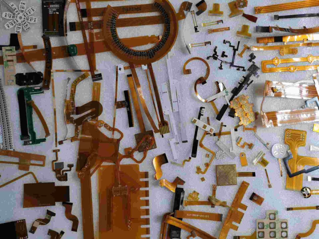
Applications of Flexible PCBs
Due to their many advantages, flex PCBs are used in a wide range of applications:
Consumer Electronics
- Cell phones
- Laptops
- Cameras
- Wearables
- VR/AR headsets
- Tablets
Flex circuits integrate neatly into tight, dynamic spaces and movable joints. The allow electronics to be lightweight and durable.
Medical Devices
- Hearing aids
- Pacemakers
- Wearable monitors
- Endoscopes
- Surgical tools
Flex boards conform to the body and fit into confined spaces within diagnostic and treatment devices.
Automotive
- Seat position sensors
- Lighting
- Dash displays
- Blind spot detection
- Engine control units
Rugged flex circuits withstand vibration while enabling sensors and connections.
Industrial
- Robotics
- Machine vision cameras
- Human-machine interfaces
- Measurement systems
Flex PCBs enable reliable interconnects for sensors, controllers, and equipment in factory automation systems.
The unique properties of flex PCB technology make it the ideal choice for integrating circuitry into the tight confines of modern electronic products and systems. As electronics become more wearable and portable, flex circuits will continue gaining popularity across nearly all industries and applications.
Flex PCB Assembly FQA
Q: What are some key considerations when designing a flex PCB?
A: Some key design considerations include:
- Layer stackup (single-sided, double-sided, multilayer)
- Conductor trace width/thickness for flexibility and current
- Minimum bend radius the PCB can tolerate
- Substrate material properties like flex life and temperature resistance
Proper design ensures the board can perform mechanically and electrically as intended.
Q: What are the main manufacturing steps to fabricate a flex PCB?
A: The main fabrication steps include:
- Imaging to create the photomask
- Lamination to stack material layers
- Etching to remove copper
- Drilling holes for vias
- Plating exposed pads and holes
- Applying solder mask and silkscreen
Automated manufacturing allows high volume production at low cost.
Q: How are components assembled onto a completed flex PCB?
A: Common assembly processes include:
- SMT to mount surface mount components
- Die attach to directly mount any bare IC dies
- Wire bonding to connect dies to pads
- Conformal coating for protection
- Testing to validate functionality
Flex boards use similar assembly as rigid PCBs but require special handling.
Q: What are some examples of flex PCB applications?
A: Flex PCBs are widely used in:
- Consumer electronics like phones, laptops, wearables
- Medical devices such as hearing aids and monitors
- Automotive sensors, lighting, displays
- Industrial automation and robotics
Their flexibility makes them ideal for tight, dynamic, portable electronics and interconnects.
Q: What specialized equipment is used in flex PCB assembly?
A: Some key flex assembly equipment includes:
- Flexible rework stations with vacuum hold-down
- Adjustable conveyors and tooling pins
- Board holders to support flex PCBs
- Flexible solder pallets for reflow ovens
- Test fixtures that allow movement and bending
This equipment streamlines flex assembly while preventing damage.


Leave a Reply