Introduction to Rigid-Flex PCBs
Rigid-Flex PCBs are a unique type of printed circuit board that combines the benefits of both rigid and Flexible PCBs. These boards consist of rigid and flexible substrates that are laminated together, allowing for a more compact and reliable design compared to using separate rigid and flexible PCBs connected by cables or connectors. Rigid-Flex PCBs offer numerous advantages, including improved reliability, reduced weight and size, and enhanced electrical performance.
What is a Rigid-Flex PCB?
A Rigid-Flex PCB is a hybrid printed circuit board that integrates both rigid and flexible substrates into a single, unified structure. The rigid sections of the board provide structural support and house most of the components, while the flexible sections allow for bending, folding, or flexing, enabling the board to fit into tight spaces or conform to unique shapes.
The flexible portions of the board are typically made from a thin, flexible polymer material, such as polyimide, which is laminated to the rigid sections using adhesive layers. The conductive traces on the flexible sections are usually made from copper, just like on the rigid sections, but they are designed to withstand the stresses of repeated flexing without breaking or losing their electrical properties.
Advantages of Rigid-Flex PCBs
Rigid-Flex PCBs offer several key advantages over traditional Rigid PCBs or separate rigid and flexible PCBs connected by cables or connectors:
-
Reduced size and weight: By integrating the flexible sections directly into the rigid board, Rigid-Flex PCBs eliminate the need for separate connectors and cables, resulting in a more compact and lightweight design.
-
Improved reliability: The elimination of connectors and cables also reduces the number of potential failure points, improving the overall reliability of the system. Additionally, the flexible sections are designed to withstand repeated flexing without damage, further enhancing reliability.
-
Enhanced electrical performance: Rigid-Flex PCBs offer better electrical performance compared to separate rigid and flexible PCBs connected by cables. The integrated design minimizes signal loss, reduces electromagnetic interference (EMI), and improves signal integrity.
-
Increased design flexibility: The ability to bend, fold, or flex the PCB allows for more creative and space-efficient designs, making Rigid-Flex PCBs ideal for applications with limited space or unique packaging requirements.
-
Reduced assembly time and cost: By consolidating multiple PCBs and connectors into a single Rigid-Flex PCB, assembly time and costs can be significantly reduced, as fewer components need to be manufactured and assembled.
Applications of Rigid-Flex PCBs
Rigid-Flex PCBs are used in a wide range of industries and applications where space constraints, reliability, and performance are critical factors. Some common applications include:
-
Aerospace and Defense: Rigid-Flex PCBs are well-suited for aerospace and defense applications, where size, weight, and reliability are paramount. They are used in avionics systems, satellites, military communication devices, and more.
-
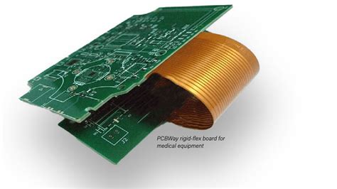
Medical Devices: The compact size and reliability of Rigid-Flex PCBs make them ideal for medical devices, such as wearable monitors, implantable devices, and diagnostic equipment.
-
Automotive Electronics: Rigid-Flex PCBs are used in various automotive applications, including infotainment systems, driver assistance systems, and engine control units, where they offer improved reliability and space savings.
-
Consumer Electronics: The compact size and design flexibility of Rigid-Flex PCBs make them well-suited for consumer electronics, such as smartphones, tablets, smartwatches, and virtual reality headsets.
-
Industrial Automation: Rigid-Flex PCBs are used in industrial automation systems, such as robotics, machine control, and data acquisition systems, where their reliability and resistance to harsh environments are important factors.

Rigid-Flex PCB Design Considerations
Designing a Rigid-Flex PCB requires careful consideration of several factors to ensure optimal performance, reliability, and manufacturability. Some key design considerations include:
Material Selection
Choosing the right materials for both the rigid and flexible sections of the board is crucial for ensuring the desired electrical, mechanical, and thermal properties. Common materials for the rigid sections include FR-4, high-Tg FR-4, and polyimide, while the flexible sections typically use polyimide or other flexible polymer materials.
The choice of copper weight and thickness for the conductive traces is also important, as it affects the electrical performance and the ability of the flexible sections to withstand repeated flexing without damage.
Bend Radius and Flexibility
The bend radius and flexibility of the flexible sections must be carefully designed to ensure the board can withstand the required number of flex cycles without failure. The minimum bend radius is determined by factors such as the thickness of the flexible material, the copper weight, and the number of layers in the flexible section.
Designers should also consider the location and orientation of components near the flexible sections to minimize stress on the components during flexing.
Layer Stack-up
The layer stack-up of a Rigid-Flex PCB is more complex than that of a traditional rigid PCB, as it must account for the transition between the rigid and flexible sections. Designers must ensure that the layer stack-up provides adequate insulation and adhesion between layers, as well as proper signal routing and grounding.
In general, the flexible sections of the board have fewer layers than the rigid sections, as the increased thickness of multiple layers can reduce flexibility and increase the risk of delamination or cracking.
Signal Integrity and EMI
Maintaining signal integrity and minimizing electromagnetic interference (EMI) are critical considerations in Rigid-Flex PCB design. Designers must carefully route signals to minimize crosstalk, signal reflections, and other issues that can degrade signal quality.
Proper grounding and shielding techniques, such as the use of ground planes, stitching vias, and shielding layers, can help mitigate EMI and ensure reliable performance.
Manufacturability
Rigid-Flex PCBs are more complex to manufacture than traditional rigid PCBs, and designers must work closely with their manufacturing partners to ensure the board can be produced reliably and cost-effectively.
Factors to consider include the selection of materials, the design of the transition zones between rigid and flexible sections, the placement of components, and the choice of surface finishes and marking methods.

Rigid-Flex PCB Manufacturing Process
The manufacturing process for Rigid-Flex PCBs is similar to that of traditional rigid PCBs but with additional steps to incorporate the flexible sections and ensure proper lamination between the rigid and flexible layers.
Step 1: Material Preparation
The first step in the Rigid-Flex PCB manufacturing process is to prepare the raw materials, including the rigid and flexible substrates, copper foils, and adhesive layers. The flexible substrate, typically a polyimide film, is pre-treated to improve its adhesion to the copper foil and the adhesive layers.
Step 2: Patterning and Etching
Next, the copper foil is laminated to the flexible substrate, and the circuit patterns are defined using photolithography and etching processes, similar to those used for rigid PCBs. The copper traces on the flexible sections are typically narrower and more closely spaced than those on the rigid sections to maintain flexibility.
Step 3: Lamination
After the circuit patterns have been defined, the flexible sections are laminated to the rigid sections using adhesive layers. The adhesive is applied to both the rigid and flexible substrates, and the layers are aligned and pressed together under heat and pressure to form a strong bond.
Step 4: Drilling and Plating
Once the rigid and flexible sections are laminated together, the board undergoes drilling and plating processes to create the vias and through-holes that connect the different layers of the board. The holes are typically drilled using laser or mechanical drilling methods, depending on the size and location of the holes.
After drilling, the holes are plated with copper to create electrical connections between layers. Additional plating processes, such as Solder Mask application and surface finishing, may also be performed at this stage.
Step 5: Cutting and Profiling
The final step in the Rigid-Flex PCB manufacturing process is cutting and profiling the board to its final shape and size. This is typically done using a combination of mechanical routing and laser cutting methods, depending on the complexity of the board shape and the required precision.
After cutting and profiling, the board undergoes a final inspection to ensure that it meets all quality and performance requirements before being packaged and shipped to the customer.

Testing and Quality Control
Ensuring the quality and reliability of Rigid-Flex PCBs requires a comprehensive testing and quality control process that covers both the rigid and flexible sections of the board.
Visual Inspection
The first step in the testing process is a visual inspection of the board to check for any obvious defects or irregularities, such as cracks, delamination, or misaligned layers. This inspection is typically performed using a microscope or other magnification tools to ensure that even small defects are detected.
Electrical Testing
After visual inspection, the board undergoes electrical testing to verify that all circuits are functioning correctly and that there are no short circuits or open connections. This testing is typically performed using automated test equipment (ATE) that can quickly and accurately test all the connections on the board.
Flexibility Testing
To ensure that the flexible sections of the board can withstand the required number of flex cycles without failure, the board undergoes flexibility testing. This involves repeatedly flexing the board to a specified bend radius and checking for any signs of damage or degradation, such as cracks, delamination, or changes in electrical performance.
Environmental Testing
Depending on the intended application, Rigid-Flex PCBs may also undergo environmental testing to ensure that they can withstand the expected operating conditions, such as temperature extremes, humidity, vibration, or shock. These tests are designed to simulate the actual use environment and verify that the board can perform reliably under those conditions.
Microsectioning
In some cases, destructive testing methods such as microsectioning may be used to evaluate the quality of the lamination between the rigid and flexible sections of the board. This involves cutting the board into small Cross-Sections and examining the interface between the layers under a microscope to check for any signs of delamination or other defects.
By subjecting Rigid-Flex PCBs to a rigorous testing and quality control process, manufacturers can ensure that the boards meet all performance and reliability requirements and are suitable for use in demanding applications.
Frequently Asked Questions (FAQ)
1. What is the difference between a Rigid-Flex PCB and a traditional rigid PCB?
A Rigid-Flex PCB combines both rigid and flexible substrates into a single, integrated board, while a traditional rigid PCB consists only of rigid substrates. The flexible sections in a Rigid-Flex PCB allow the board to bend, fold, or flex, enabling more compact and space-efficient designs.
2. What are the main advantages of using Rigid-Flex PCBs?
The main advantages of Rigid-Flex PCBs include reduced size and weight, improved reliability, enhanced electrical performance, increased design flexibility, and reduced assembly time and cost compared to using separate rigid and flexible PCBs connected by cables or connectors.
3. What industries commonly use Rigid-Flex PCBs?
Rigid-Flex PCBs are used in a wide range of industries, including aerospace and defense, medical devices, automotive electronics, consumer electronics, and industrial automation, where space constraints, reliability, and performance are critical factors.
4. What are some key design considerations for Rigid-Flex PCBs?
Key design considerations for Rigid-Flex PCBs include material selection, bend radius and flexibility, layer stack-up, signal integrity and EMI, and manufacturability. Designers must work closely with their manufacturing partners to ensure that the board can be produced reliably and cost-effectively.
5. How are Rigid-Flex PCBs tested to ensure quality and reliability?
Rigid-Flex PCBs undergo a comprehensive testing and quality control process that includes visual inspection, electrical testing, flexibility testing, environmental testing, and, in some cases, destructive testing methods such as microsectioning. This rigorous testing ensures that the boards meet all performance and reliability requirements and are suitable for use in demanding applications.
Conclusion
Rigid-Flex PCBs offer a unique combination of the benefits of both rigid and flexible PCBs, enabling more compact, reliable, and high-performance electronic designs. By integrating flexible sections directly into the rigid board, Rigid-Flex PCBs eliminate the need for separate connectors and cables, resulting in reduced size, weight, and complexity.
The design and manufacturing of Rigid-Flex PCBs require careful consideration of factors such as material selection, bend radius, layer stack-up, signal integrity, and manufacturability. Close collaboration between designers and manufacturing partners is essential to ensure that the boards can be produced reliably and cost-effectively.
As electronic devices continue to become smaller, more complex, and more demanding in terms of performance and reliability, the use of Rigid-Flex PCBs is likely to increase across a wide range of industries and applications. By understanding the capabilities, advantages, and design considerations of Rigid-Flex PCBs, engineers and designers can create innovative and high-performance electronic products that meet the evolving needs of their customers.


Leave a Reply