What is a flex PCB?
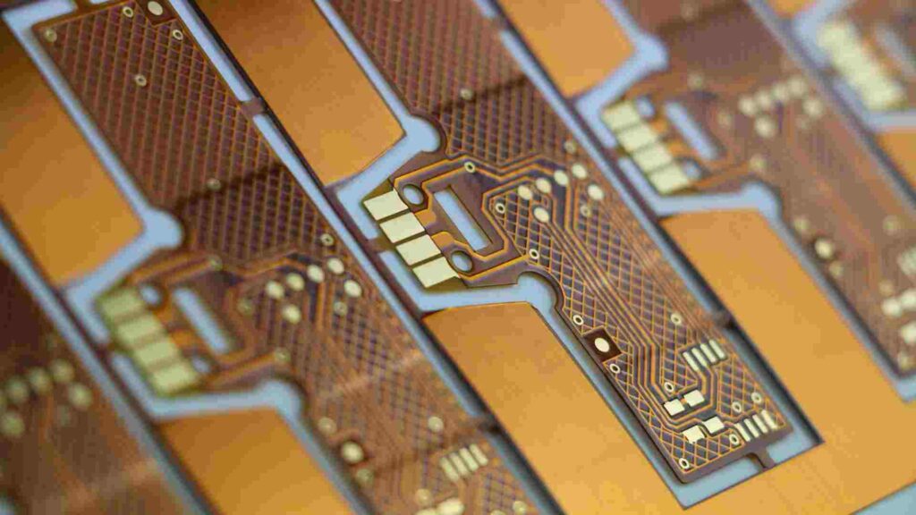
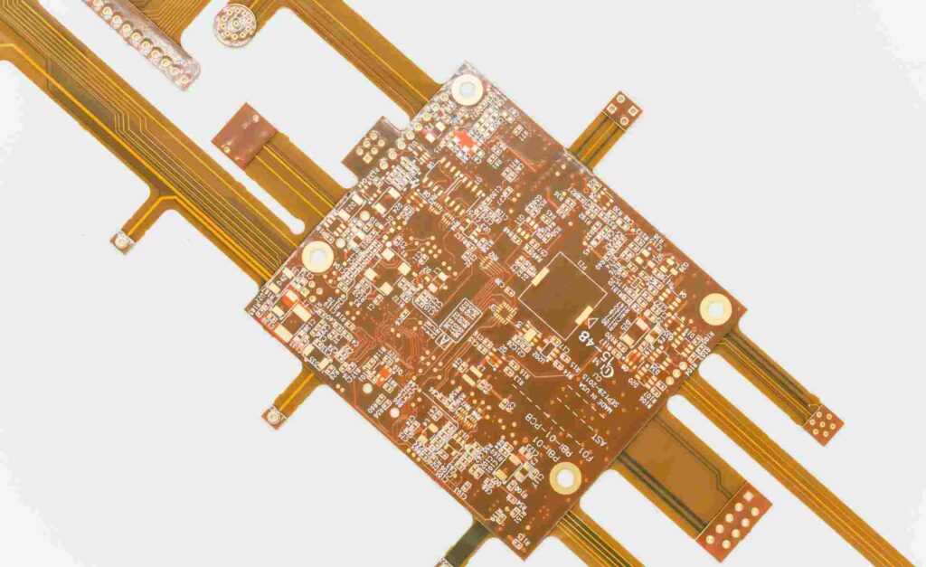
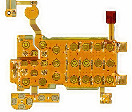
A flex PCB, or flexible printed circuit board, is a type of printed circuit board that is made of flexible insulating material rather than rigid FR-4 material. The circuits are printed or etched onto the flexible substrate which can then be bent and folded to fit into tight or movable spaces.
Flex PCBs provide several advantages over rigid PCBs:
- They can flex and bend, allowing them to fit into tight spaces and movable parts
- They are lightweight and thin
- They can withstand vibration and impact better than rigid boards
- They allow for complex and compact 3D routing of traces
- They are ideal for products where flexibility and movability are required
Common applications of flex PCBs include wearable devices, medical devices, consumer electronics, aerospace and automotive. The flexible nature allows them to move, bend and shape to the required form factor.
What determines the number of layers?

There are several factors that determine how many layers a flex PCB can have:
1. Flexibility requirements
The more layers in a flex PCB, the less flexible it becomes. If maximum flexibility is required for tight bend radii or dynamic flexing, typically only 1-4 layers would be possible. Applications like pagers or wearable may only require 1-2 flexible layers.
2. Circuit complexity
More complex and dense circuits with many traces and components require more routing layers. High performance or complex flex PCBs can have 6-12 layers or even more.
3. Board thickness
The thickness of each conductive layer and insulating dielectric material adds up. With more layers, the flex PCB thickness increases, impacting flexibility and bend radius. Thinner dielectric materials allow more layers in a given thickness.
4. Manufacturing capabilities
The number of layers is also limited by the capabilities of the flex PCB manufacturer. Currently flex PCBs are commonly produced with 2 to 12 layers, though some manufacturers can go higher.
5. Cost
Increasing the layer count makes the flex PCB fabrication more complex and costly. So the number of layers is also determined by budget considerations.
Typical Layer Counts
Here are some typical layer counts and configurations used in different types of flex PCBs:
| Application | Typical Layer Count |
|---|---|
| Simple wearables | 1-2 layers |
| Consumer electronics | 2-6 layers |
| Dynamic flexing | 2-4 layers |
| High density interconnect | 6-12 layers |
| Medical devices | 4-8 layers |
| Automotive | 6-12 layers |
| Aerospace | 6-12 layers |
Maximum Flex PCB Layers

Most manufacturers can reliably produce flex PCBs with up to 12 layers at reasonable yields and costs.
Some manufacturers using advanced processes and dielectric materials can go higher – producing flex PCBs with 16, 18 or even 20 conductive layers for extremely complex and dense flex circuits.
One technology that allows more layers is the use of “stacked vias”. This allows traces to route between non-adjacent layers, skipping over some layers in between. This provides greater layout flexibility with dense multi-layer boards.
FQA:
How does number of layers affect cost and lead time?
In general, increasing the layer count in a flex PCB will increase its cost and lead time. Each additional conductive layer adds additional process steps of laminating, drilling, plating, etc. The more complex fabrication also affects yields and requires more inspection and testing time. For simple 1-2 layer boards, costs and lead times can be very low. But for complex boards with 12 or more layers, both costs and lead times increase considerably.
Can I mix rigid and flex layers in one PCB?
Yes, many designs utilize rigid-flex PCBs which combine both rigid FR-4 layers and flexible dielectric layers. The rigid sections provide structure and component mounting, while the flex layers connect and route through dynamic portions of the circuit. Rigid-flex allows the benefits of flex PCBs while keeping some areas rigid for stability and mounting.
What are some key design rules for flex PCBs?
Some key guidelines when designing flex PCBs are:
- Avoid 90 degree angles on traces – use rounded curves instead
- Avoid rigid components in the flexing portion
- Allow sufficient bend radius for flexibility required
- Use teardrop pads and rounded solder mask openings
- Analyze dynamic and static flexing aspects
- Minimize layers for highly dynamic flexing
Following flex PCB design rules helps ensure the boards will be manufacturable and withstand the required dynamic bending.
How do I select a flex PCB manufacturer?
Some tips for selecting a good flex PCB manufacturer:
- Make sure they have expertise specifically with flex PCBs
- Ask about their layer count capabilities and minimum bend radii
- Review their design rule guides for flex PCBs
- Look at their reliability certifications (ISO, etc)
- Evaluate their manufacturing capacities and lead times
- Examine their quality control and inspection processes
- Require coupons and samples for your specific project
- Get references from prior customers with similar projects
How flexible can the most flexible flex PCB get?
The flexibility of a flex PCB depends on several factors like number of layers, dielectric material, copper thickness, and bend radius. The most flexible circuits use thin polyimide dielectric layers around 12-25um thick, single layered, 1/3 oz copper, and dynamic flexing down to a 0.5mm radius. By optimizing these parameters, flex PCBs can achieve remarkably dynamic bending into very tight radii.


Leave a Reply