Introduction to Flex Circuits
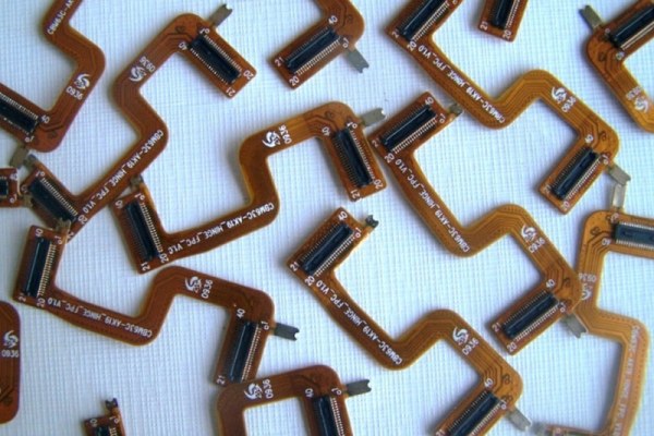
Flexible printed circuits (FPCs), also known as flex circuits, are made from flexible polymer substrates that have conductive circuits printed or bonded onto them. The circuits can bend, twist, and flex during use without losing electrical connectivity. This makes flex circuits ideal for applications where flexibility, space savings, and mechanical durability are needed.
Flex circuits are commonly used in consumer electronics, medical devices, automotive systems, aerospace applications, and more. They allow circuitry to fit into tight or moving spaces that would be impossible with rigid boards. Their flexibility also reduces system weight and increases reliability by absorbing stresses and vibrations.
In this article, we will provide an overview of flex circuit design considerations, manufacturing processes, and advantages compared to rigid PCBs.
Design Factors for Flex Circuits
Several key factors need to be considered when designing a flex circuit:
Substrate Material
The substrate or base material for FPCs is typically a thin polymer film such as polyimide, polyester, or PEN. Polyimide films like Kapton offer high heat resistance and mechanical strength. The thickness ranges from 12.5 to 100 microns. The thinner the material, the more flexible the circuit can be.
Conductor Material
Copper is most commonly used due to its high conductivity and flexibility. Other options include aluminum, nickel, gold, or silver. The conductors are either laminated onto the substrate as rolled annealed copper foil or deposited through plating or printing.
Dielectric Material
The dielectric insulates between conductors on the circuit. Common options are acrylic, polyimide, epoxy, PET, or PTFE. The dielectric constant impacts electrical performance.
Layer Stackup
Most flex circuits are single or double sided, but multilayer configurations with 3-12 layers are possible. adhesive holds the layers together. Vias and plated through holes connect layers electrically.
Bend Radius
The minimum bend radius dictates the flexibility. Smaller bend radii allow tighter folding but increase stresses. Typical bend radii range from 2 to 10 times the total board thickness.
Stiffeners
Areas that do not flex can use stiffeners made of materials like polyimide for structural support. Stiffeners prevent damage from handling or vibration.
Flex Circuit Manufacturing Processes
There are several steps to manufacturing flex circuits:
Imaging
A photoresist coating is applied to the substrate. It is then exposed to UV light through a mask. Developing removes the unexposed photoresist, leaving a patterned mask for etching.
Etching
This removes unwanted copper from the substrate to form the circuit traces and pads. Common etching methods are chemical etching, plasma etching, or laser ablation.
Plating
Electrolytic plating can build up copper thickness in the traces or plate tin, nickel, or gold over the pads and contacts.
Lamination
Layers of substrate, adhesive, and often copper foil are stacked and laminated under heat and pressure to bond them together.
Drilling
Mechanical drilling or laser drilling makes the holes needed for vias that interconnect layers. The walls are plated with copper.
Testing and Finishing
Each circuit is electrically tested. A soldermask coating and surface finish are applied. The boards are separated by shearing or routing.
Benefits of Flex Circuits
Compared to traditional rigid printed circuit boards, flexible circuits provide several advantages:
- Flexibility – Can bend and flex repeatedly to fit demanding shape requirements
- Thin profile – As thin as 1 mil allows compact, lightweight systems
- Durability – Withstands millions of dynamic flex cycles without failure
- Weight savings – Lighter than rigid boards due to lack of rigid frame
- Reliability – Absorbs vibrations and stresses preventing failures
- Higher frequencies – Low dielectric loss allows high frequency operation
- 3D assembly – Can be folded or wrapped into 3D configurations
- Design freedom – Circuits can be dynamically flexed or folded as part of the design
- Robust connections – Micro-vias provide robust interconnects between layers
With thoughtful design, flex circuits can meet the needs of many demanding applications where rigidity and space are concerns.
Typical Applications of Flexible Circuits
Some of the many uses for flex circuit technology include:
- Consumer electronics – Cell phones, laptops, tablets, cameras
- Automotive – Sensors, control modules, LED lighting
- Medical – Hearing aids, pacemakers, imaging systems
- Aerospace and military – Guidance systems, engine controls, radar
- Robotics – Arms and joints that require flexing
- Wearables – Fitness trackers, health monitors, smart glasses
- Instrumentation – Probes, sensors, detectors
Flex circuits are often designed for dynamic flexing during normal operation. For example, flex cables connecting computer components allow constant motion without failure. They also provide interconnects between rigid subassemblies.
Design Guidelines for Optimal Flex Circuits
Follow these guidelines for the best performing and most reliable flex circuit designs:
- Minimize unsupported spans between stiffeners
- Avoid sharp folds – use generous bend radii
- Symmetrically laminate conductive layers on both sides
- Adhere to minimum trace width/spacing rules
- Ensure sufficient bondpad adhesion strength
- Include strain relief features at connectors
- Select stable, heat-resistant substrate materials
- Protect components with soldermask coating
- Prevent exposure to harsh chemicals or extreme temperatures
- Model dynamic and static flexure effects with FEA
Careful thermal and mechanical modeling ensures the circuitry withstands the application demands across the entire lifetime.
Trends in Flexible Circuit Technology
Some current trends taking flex circuit technology further include:
- Extremely thin circuits – Below 10 microns
- Stretchable circuits – Embedded conductors survive stretching
- Flex-to-fit boards – Can conform to complex 3D shapes
- Rigid-flex – Combines rigid sections with flexible folds
- Additive processing – Builds up circuits by printing conductive inks
- Embedded passives – Passive components within the layers
- Flexible hybrid electronics – Combines flex circuits with chips
- Roll-to-roll processing – Continuous production of circuits
Continued innovation and adoption will open up new possibilities for flex circuits and flexible electronics in general. The future is flexible!
Frequently Asked Questions
What are some typical specifications on a flex circuit design?
Typical specifications include the substrate material and thickness, minimum trace width/spacing, minimum bend radius, number of layers, stiffness, dielectric type, and copper thickness. Environmental factors like operating temperatures are also important.
Can components be mounted directly on flex circuits?
Yes, both surface mount and through-hole components can be mounted, but may require special design considerations. Adhesives are used to strengthen solder joints. Flexible encapsulants protect components.
How are connections made to a flex circuit?
Connections use technologies like soldered pads, sockets, crimped terminals, anisotropic conductive film, or mechanical clamping. Careful strain relief design is critical.
What are some failure modes in flex circuits?
Common failure modes are conductor cracks due to repeated dynamic flexing, delamination between layers, broken plated through holes, and cracked solder joints. Careful design minimizes these risks.
How do costs compare between rigid and flex PCBs?
Flex circuits require specialized materials and processes, so costs are typically higher per unit area compared to rigid boards. But the total system cost may be lower when space, weight, and assembly savings are considered.


Leave a Reply