Introduction
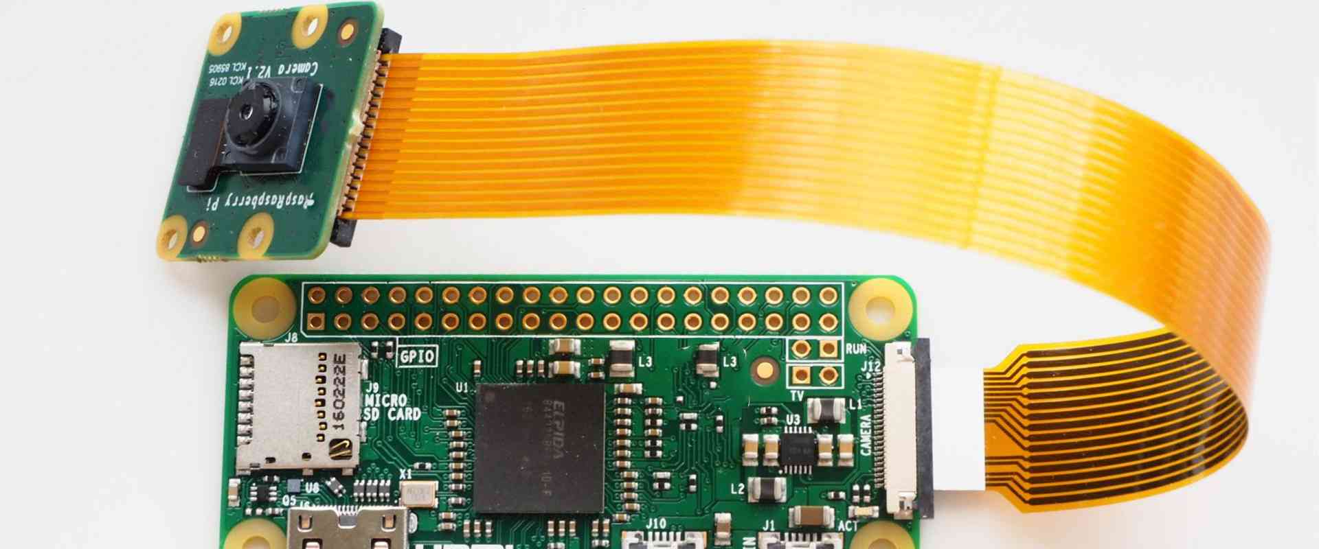
A flexible printed circuit board (FPCB), also known as a flex circuit, is a type of printed circuit board made from flexible polymer substrates like polyimide or polyester. Unlike traditional rigid PCBs, flex circuits can bend and flex to accommodate different form factors and spaces. Flex circuits are ideal for electronic devices with moving parts or dynamic configurations like wearables, IoT devices, consumer electronics, automotive electronics, aerospace avionics, and medical devices.
Flex circuits provide several advantages over rigid boards:
- Extremely thin, lightweight, and flexible to fit into tight spaces
- Can conform and flex with moving parts
- Highly durable and resistant to cracking with dynamic flexing
- Allow for greater miniaturization of electronics
- Enable innovative and ergonomic product designs
- Often lower costs compared to rigid-flex designs
In this comprehensive guide, we’ll explore everything you need to know about flex PCB design, materials, manufacturing, assembly, and applications.
Flexible PCB Design
Flex circuit layouts and designs can be complex, requiring specialized design skills and PCB design software. Here are some key design considerations for flex circuits:
Layer Stackup
Determining the right layer stackup is crucial for balancing flexibility, signal integrity, and manufacturability. Common flex stackups include:
- Single-sided: Cu layer on one side only
- Double-sided: Cu layers on both sides
- Multilayer: 3+ conductive layers separated by dielectric
Conductor Spacing and Width
Narrow trace and space is important for flexibility. Typical widths are:
- Fine Line: trace/space ≤ 100μm
- Ultrafine Line: trace/space ≤ 50μm
Wider traces may be required for high power transmission.
Bend Radius
A minimum bend radius restricts the flexing to prevent trace cracking. Typical minimum bend radii range from 3x to 10x the board thickness.
Stiffeners and Shielding
Stiffeners and shields are used to control flexibility in certain areas. Common options:
- Coverlay: Laminated shielding layer
- Metal stiffeners: Rigid sections for connectors
- Covers: Plastic or metal shields for protection
Adhesives
Adhesives attach flex circuits and maintain alignment with other components. Considerations include flexibility, thickness, and bonding method.
Vias and Holes
Blind and buried vias can connect layers internally. Holes may be necessary for alignment pins or fasteners.
Testing
Test coupons validate minimum bend radius. Electrical testing checks for opens, shorts, and impedance.
Flex Circuit Materials
Choosing the right materials is crucial for optimizing flexibility, performance, and reliability. Here are some of the main options:
Substrates
The base material determines flexibility, temperature resistance, chemical resistance, dielectric properties, and cost. Common substrates:
- Polyimide (PI): Most common. Withstands high temps. Good chemical resistance.
- Polyester (PET): Lower cost. Limited temperature resistance.
- PEN: High temp rating. Expensive. Used for LCDs.
- LCP: Extremely high temps. Chemically inert. Costly.
- Peek: Semicrystalline. Withstands high temps. Chemically resistant.
Coverlay
Coverlay is a flexible dielectric laminated over traces for insulation and protection. Common options:
- Liquid Photoimageable Coverlay (LPI): Provides high resolution, excellent processing, and high bond strength.
- Thermoset Epoxy Acrylic: More economical. Limited processing capability.
Bonding Adhesives
Adhesives bond layers and provide environmental protection. Options include acrylic, epoxy, silicone, and pressure sensitive adhesives (PSA).
Conductors
Copper foil is most common for traces and pads. Options vary in thickness, electrodeposited vs rolled copper, and surface treatment.
Flex PCB Manufacturing Process
Producing flex circuits requires specialized manufacturing equipment and processes. Here is a high-level overview:
Imaging
The circuit layout artwork is transferred to the photosensitive copper laminate using photolithography.
Etching
Unwanted copper is etched away to form the traces and pads.
Dielectric Lamination
Coverlay or bonding sheets are laminated onto surfaces for insulation and protection.
Via Formation
Vias are formed through the dielectric using laser ablation or plasma etching. Metallization coats the interior walls.
Plating and Coating
Surfaces are plated with solder, tin, or gold. Covercoats and solder masks are applied.
Sizing
Blanks are cut to size using dies or lasers. Slitters cut into individual circuits.
Testing and Inspection
100% electrical testing and visual inspection ensures quality and reliability.
Flex Circuit Assembly
Population of components requires specialized assembly processes:
SMT Assembly
SMD components are mounted on flex circuits using solder paste and reflow soldering. Fine features require advanced pick and place systems.
Terminations
Connections are made by soldering or crimping terminals, pins, or wires to pads. Anisotropic conductive films can also connect components.
Adhesive Attachment
Flip chips, connectors, and other components are fixed with conductive or non-conductive adhesive.
Staking and Potting
Wire relief, strain relief, and ventilation are added by staking, potting, or underfill materials.
Encapsulation
Conformal coatings and potting compounds protect against dust, moisture, vibration, and other environmental factors.
Flex Circuit Applications
Some common product applications for flex circuits include:
Consumer Electronics
- Displays (OLED, LCD)
- Smartphones, tablets, laptops
- Wearable devices
- Virtual reality
- Printers, disk drives
Automotive & Transportation
- Automotive sensors
- Hybrid/electric vehicle circuitry
- Infotainment displays
- GPS navigation systems
- Engine control units
- Airbag systems
Medical
- Hearing aids
- Diagnostic imaging flex assemblies
- Surgical devices
- Patient monitoring
- Implantable devices
Aerospace & Defense
- UAVs, drones, missiles
- Avionics systems
- Radar and antennas
- Spacecraft flex interconnects
Industrial
- Robotics/motion control
- Thermal printers
- Motor/pump control
With their thin, lightweight, and dynamic form factors, flex circuits open up innovative design possibilities across practically every industry and application. Continued technology improvements in flex materials, stackups, and manufacturing will enable ongoing miniaturization and performance advances for electronics.
Flexible Circuit Board FAQs
Here are answers to some frequently asked questions about flex PCBs:
What are the main advantages of using a flex circuit?
Flex circuits are thin, lightweight, and can conform to tight spaces and moving parts. This allows for miniaturization, ruggedization, simplified assembly, improved reliability, and innovative ergonomic designs not possible with rigid boards.
How flexible can flex circuits be?
Flexibility depends on the material stackup and minimum bend radius, but flex circuits can be bent to a radius even lower than 10 times the thickness. Some circuits can endure over a million dynamic flex cycles.
Are flex circuits more expensive than rigid PCBs?
Not always. For very simple designs, rigid PCBs may be cheaper. But for complex layouts, flex circuits can cost less because they require fewer interconnects and joints. The value from space savings and improved reliability also offset costs.
What are some guidelines for designing a flex circuit?
Use minimum trace widths and spaces, control flexibility with stiffeners, minimize component holes, watch for impedance issues, include test coupons, and work closely with your flex PCB manufacturer during design.
How are components assembled onto flex circuits?
SMT, adhesive attachment, solder termination, anisotropic films, and other methods are used. Care must be taken during assembly to avoid damaging the thin, flexible boards.
Conclusion
With their dynamic bendability, durability, and design flexibility, flex circuits are enabling electronics miniaturization across practically every industry and application. As a PCB designer, it’s important to understand the specialized materials, design rules, manufacturing processes, and assembly procedures for working with flex circuits in order to take advantage of their unique benefits. Collaborating closely with an experienced flex circuit manufacturer is crucial for designing and producing a reliable, high-performing flex PCB assembly.


Leave a Reply