Overview of Flex PCBs
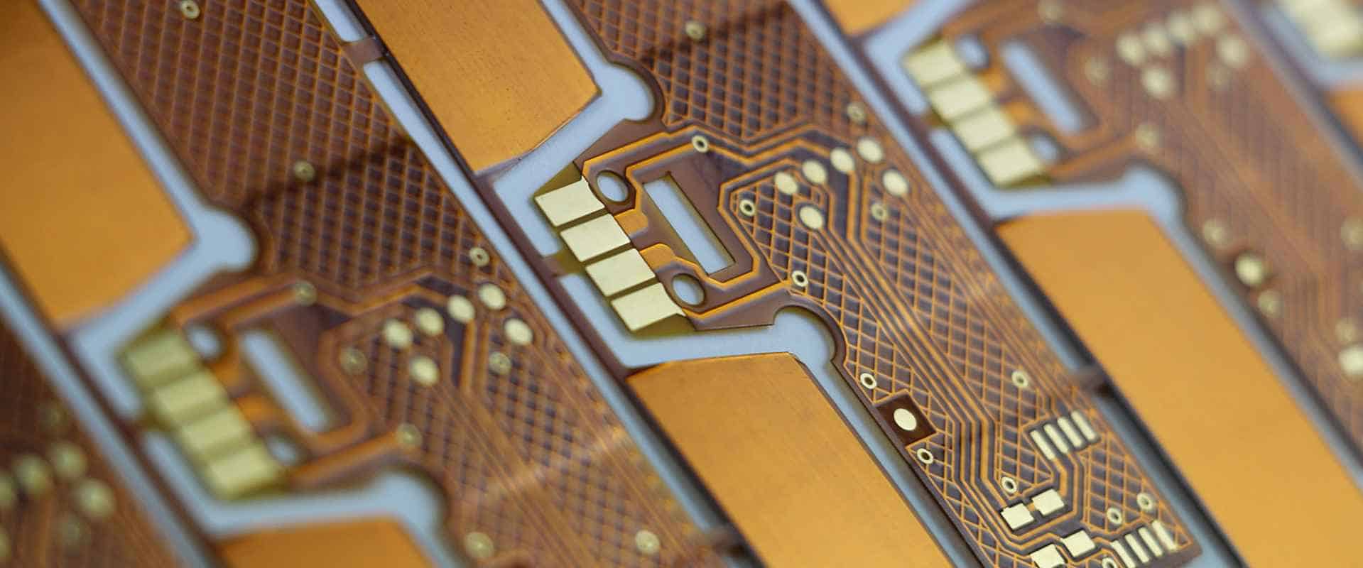
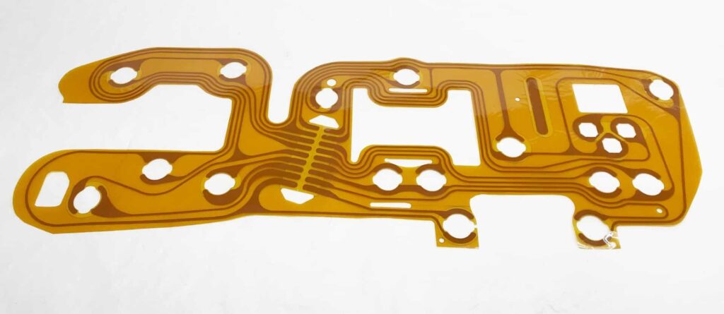
A flexible printed circuit board (flex PCB or flex circuit) is a type of printed circuit board that is made of flexible materials such as polyimide. Unlike rigid PCBs, flex PCBs can bend and flex while still maintaining their electrical connections. This allows them to be used in applications where a rigid board would be impractical.
Some key advantages of flex PCBs:
- Can flex and bend to accommodate different product shapes and motions
- Lightweight and takes up less space compared to rigid PCBs
- Allows for motion/vibration control and dynamic flexing environments
- Can be manufactured in very thin profiles (as low as 1 mil)
- Often used to connect multiple rigid PCBs together
Common applications of flex PCBs include wearable devices, medical devices, consumer electronics, automotive electronics, aerospace avionics, and more. The flex PCB manufacturing process has some key differences from the standard rigid PCB fabrication process.
Flex PCB Manufacturing Process Steps
The main steps in manufacturing a flex PCB include:
1. Design and Layout
The flex PCB layout is designed in CAD software. Considerations at this stage include:
- Circuit routing to accommodate bending and folding
- Minimizing rigid sections for maximum flexibility
- Allowing for dynamic flexing or static bends
- Avoiding sharp bends or tearing in high-stress areas
- Minimizing crossovers between layers
2. Material Selection
The flex circuit material is typically a polyimide film such as Kapton with a thickness from 1 to 5 mils. Thinner material allows for tighter bends. Bonding films and stiffeners may be added for multilayer boards.
3. Imaging and Etching
A photoresist is applied to the copper clad laminate and imaged to transfer the circuit pattern. The exposed copper is then etched away, leaving the desired traces.
4. Die Cutting
The individual flex PCBs are cut apart from each other if being batch fabricated. V-scoring may be added to facilitate folding along certain lines.
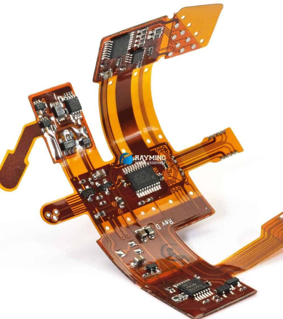
5. Assembly
Electronic components are assembled onto the PCB using soldering, conductive epoxy, or mechanical connections. Stiffeners may be added to aid assembly.
6. Encapsulation
A protective coating may be applied to prevent corrosion, insulate traces, or limit flexing in certain areas. Common coatings are solder mask, silicone, urethane, and paraxylene.
7. Testing and Inspection
Each completed flex PCB goes through electrical testing, visual inspection, and often x-ray or AO1 to ensure quality before shipment.
Below is a table summarizing the key steps in the flex PCB fabrication process:
| Step | Description |
|---|---|
| 1. Design and Layout | CAD design with considerations for flexing, bending, layer stackup |
| 2. Material Selection | Polyimide films like Kapton, bonding films, stiffeners |
| 3. Imaging and Etching | Photoresist applied, imaged, developed, copper etched |
| 4. Die Cutting | Individual PCBs cut apart, v-scoring added |
| 5. Assembly | Soldering components, adding stiffeners |
| 6. Encapsulation | Protective coatings like solder mask, silicone, urethane |
| 7. Testing and Inspection | Electrical testing, visual check, x-ray/AOI |
Key Differences from Rigid PCB Fabrication
While the overall PCB fabrication process is similar, there are some key differences when manufacturing flex circuits versus rigid boards:
- Materials – Flex PCBs use flexible polyimide films instead of rigid FR-4. Bonding films and stiffeners may be incorporated as well.
- Layers – Flex circuits typically have 1-4 layers, while rigid boards can have many more layers. Too many layers can limit flexibility.
- Traces – Traces are typically wider and spacing is larger on flex PCBs to accommodate repeated dynamic flexing.
- Adhesives – Soft adhesives are used between layers rather than rigid lamination.
- Assembly – Component attachments must accommodate movement – solder joints can crack on flexing.
- Testing – In addition to electrical testing, flex PCBs also undergo repeated flexure testing.
Design Rules and Guidelines
To ensure a successful flex PCB design, here are some key guidelines to follow:
- Minimize rigid sections and maximize flex zones
- Avoid sharp 90° bends – use rounded corners with large radii
- Spread traces apart with larger spacing than on rigid boards
- Use tear-stop features at interfaces between rigid and flex areas
- Place components in periodic arrays for even stress distribution
- Add stiffeners and shields to prevent unwanted movement
- Allow for thermal expansion of metal traces under dynamic flexing
Following these guidelines helps prevent common failures like cracked traces and pads, broken plated through holes, and fractured solder joints.
Benefits of Working with a Flex PCB Manufacturer
Trying to produce flex PCB prototypes in-house can be challenging without the right specialized equipment and expertise. Working with an experienced flex PCB manufacturer provides many benefits:
- Experience – They have engineered countless flex PCB designs and know how to avoid common pitfalls.
- Capabilities – Access to advanced machinery and processes specifically for high-precision flex fabrication.
- Quality – Flex PCB suppliers have quality control procedures tailored for flexible circuits.
- Prototyping – Get high-quality flexible circuit prototypes produced quickly.
- Supplier Relationships – Leverage preferred pricing and lead times through their supplier networks.
- One-Stop-Shop – Many offer assembly, testing, and other services beyond just bare board fabrication.
Finding the right flex PCB partner helps ensure you get a high-quality flex circuit design manufactured smoothly and efficiently.
Flex PCB Assembly Considerations
In addition to the base PCB fabrication, assembling components onto the flex board brings additional considerations:
- Component types – Avoid large, tall, or heavy components that add rigidity or are prone to detachment with flexing.
- Interconnects – Solder joints are susceptible to cracking on dynamic flex circuits – alternatives likeconductive adhesive or crimped connections provide more flexure tolerance.
- Stiffeners – Strategically placed stiffeners can be used to mount components while still allowing required flex zones.
- Harnesses – Wiring harnesses with discrete wires can interface rigid components with the flexing board.
- Encapsulation – Conformal coatings reinforce solder joints and protect against environmental factors.
- Qualification – Extensive bend cycle testing qualifies the design for reliability over the required motion cycles.
Careful planning of the assembly process helps produce a robust, reliable flex circuit that withstands the required dynamic flexing over its lifetime.
Flex PCB vs Rigid-Flex
While a pure flex PCB provides maximum flexibility, sometimes a combination of rigid and flex materials is needed. This is referred to as a rigid-flex PCB.
Some key differences between pure flex PCBs and rigid-flex boards:
| Flex PCB | Rigid-Flex PCB |
|---|---|
| Made only with flexible materials like polyimide | Combines rigid board sections (FR-4) with flexible sections |
| Can continuously bend and flex repeatedly | Rigid regions provide mounting stability while flexible sections allow movement |
| Very lightweight and thin | Heavier and thicker due to presence of rigid parts |
| Lower complexity, usually 1-4 layers | Can have 10+ layers by combining rigid multilayer with thinner flex layers |
| Mainly used when uniform flexibility is required | Used when both rigid and flex regions are needed in one assembly |
Rigid-flex combines the benefits of both types of boards and allows integrating flex PCBs into products needing partial rigidity. The manufacturing process requires precise alignment between the materials.
Quality Control and Testing
To confirm a flex PCB meets all requirements, several testing and inspection procedures may be used:
- Visual inspection – Microscope examination to check trace integrity, spacing, alignment, etc.
- Electrical testing – Using flying probe or bed-of-nails testers to verify electrical connectivity.
- X-ray – Looks for internal defects like voids in adhesive layers.
- AOI – Automated optical inspection checks for surface flaws.
- Flexure testing – Subjects PCB to many repeated bend cycles to qualify reliability.
- Impedance testing – For high frequency designs, measures impedance of traces.
- Cross section – Cutting cross-sectional samples to inspect internal structure.
Extensive testing gives confidence that the flex PCBs will function properly under continuous dynamic bending.
FAQ
What are some typical applications for flex PCBs?
Some of the most common applications are wearable devices, medical devices, consumer electronics, automotive electronics, military/aerospace systems, robotics, and instrumentation.
What types of electronic components can be used on flex PCBs?
Lightweight surface mount devices are preferred. Avoid large connectors, tall components, heavy parts, or batteries that add rigidity. Discrete wiring can be used to connect more rigid components.
How small can flex PCB traces be?
Trace widths can be under 3 mils, but 5 mil traces are more common. Narrower traces increase risk of damage during repeated flexing.
How many times can a flex PCB be flexed before failure?
Properly designed flex PCBs can withstand hundreds of thousands to millions of dynamic flex cycles, depending on materials and trace design rules followed.
How should I handle and store flex PCBs?
Avoid any sharp bends or kinks beyond the specified bend radius. Store in flat or rolled formats to prevent deforming. Use protective films, tubes, or rigid covers to prevent damage.
Conclusion
Flex PCBs provide many advantages when an application requires continuous dynamic flexing or fitting into non-planar spaces. By following sound design principles and working with an experienced flex PCB manufacturer, high quality and reliable flexible printed circuit boards can be fabricated. Careful component selection and assembly is needed to produce a finished product that withstands repeated bending motions over its lifetime. With rigorous inspection and testing methods, flex PCBs can meet the demanding requirements of medical, consumer, automotive, aerospace, and many other applications needing flexible and movable electronics.


Leave a Reply