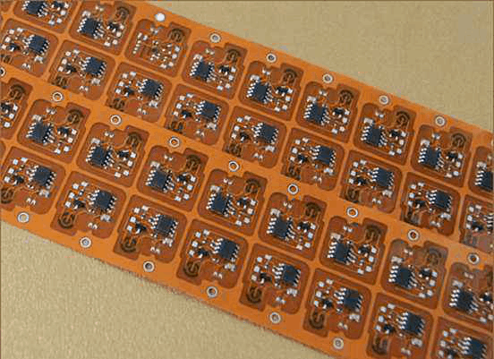
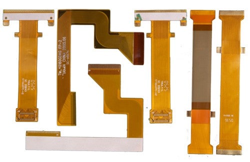
Introduction to Flexible PCBs
A flexible printed circuit board (PCB), also known as a flex circuit or flexible circuit, is a type of circuitry made from flexible materials such as polyimide or polyester. Unlike rigid PCBs made from materials like FR4, flex circuits can bend and flex while still maintaining their electrical connectivity. This makes them useful for applications where flexibility, space savings, or movement is required. Some key advantages of flexible PCBs include:
- Flexibility – Can be bent and folded to fit into tight spaces and move within enclosures. Useful for wearables, medical devices, consumer electronics.
- Space savings – Flex circuits fold up taking less space than rigid boards. Allows for smaller and lighter end products.
- Reliability – Flexible materials resist cracking and peeling from repeated bending. Vibration resistant.
- Design freedom – Flex circuits can take any shape, with traces folding around corners. Enables innovative and compact product designs.
- Lightweight – Weigh less than rigid boards, important in portable and weight-sensitive applications.
- Thin profiles – Extremely thin flex circuits enable ultra-slim product designs.
Some common applications that benefit from using flexible PCBs are wearable devices, medical electronics, robotics, foldable/bendable consumer gadgets, IoT sensors, antennas, and more.
Flex Circuit Materials and Construction

The base material for the flex circuit is a type of flexible plastic film such as polyimide or polyester. These films range from 12.5 to 100 microns thick. Components and conductive traces are bonded and etched onto the base film.
Cover layers: Flexible solder mask and coverlay films laminated over traces provide protection and insulation. Common solder mask colors are green and blue.
Adhesives: Acrylic or epoxy adhesives stick the layers together. Adhesives need to balance flexibility with bond strength.
Conductors: Copper traces carry current. Trace thickness ranges from 1/2 oz (17um) to 2 oz (70um) copper depending on current loads. Some flex circuits also use aluminum conductors.
Terminations: Pads, lands, and exposed copper provide connection points for soldering or attaching connectors. Plated gold or tin over copper prevents oxidation.
Stiffeners: Additional polyimide, polyester, or FR4 layers added in select areas reinforce flex circuits for components or connectors.
Coatings: Cover coats like liquid photoimageable (LPI) solder masks, acrylics, urethanes or other coatings protect conductors.
Flex Circuit Design Considerations
Designing a reliable, manufacturable flex circuit requires understanding the intricacies of flexible PCB technology and working closely with your flex PCB manufacturer. Here are some key design considerations:
- Bend radius – Avoid tight folds. Use the manufacturer’s minimum bend radius to prevent copper cracking. Radius depends on materials.
- Layer stackup – Stagger the placement of adhesive layers to prevent sheer stress cracks. Include stiffeners as needed.
- Conductor width/spacing – Follow manufacturer guidelines for line width, spacing to prevent shorts, cracks from conductor movement and heat buildup.
- Component placement – Strategically place components to minimize flexing stress. Use adhesive or hardware to reinforce.
- Board relief – Allow space for controlled folding and bending along intended creases without compromising traces.
- Strain relief – Provide stress relief for traces at board interfaces using graduated zigzag or curved trace geometries.
- Connections – Use flexible circuits for dynamic sections, and transition to rigid PCBs for connections. Avoid flex-to-flex.
- ESD protection – Static charges can destroy circuits. Use proper ESD handling, grounded wrist straps, mats.
- Thermal management – Carefully consider power densities. Use thermal adhesives or metal backing layers for heat dissipation if needed.
Working closely with an experienced flex PCB manufacturer during the design stage helps avoid many of these potential issues later on. They can provide design rule checks and recommendations tailored to your particular project requirements.
Flexible PCB Manufacturing Process
Producing a flexible PCB requires specialized fabrication processes and equipment. Here is a simplified overview of the flex manufacturing process:
- Design – Create circuit designs and board layouts in CAD software. Work with manufacturer on design review.
- Film Processing – Laminate multiple layers of base film, adhesive, stiffeners using thermal and pressure rollers. Photoimage solder mask, coverlay, bond adhesive layer.
- Imaging – Laminated material is coated with photoresist. Expose with UV through the copper layer artwork film.
- Etching – Unexposed copper is etched away chemically, leaving desired copper traces/pads on the base film.
- Solder mask – LPI solder mask layer is laminated and imaged for soldering, assembly.
- Testing – Bare circuits are electrically tested for continuity, shorts. Test coupons also evaluated for adhesion, flexibility.
- Finishing – Circuits are routed, trimmed. Connectors, pins are soldered if required. Final testing performed.
- Quality Assurance – Sampling inspection for defects done during production and final QA prior to shipment.
The specialized machines and engineering expertise required for flex PCB fabrication make volume production economical. Prototyping in small batches is very feasible as well. Discuss options with your flex circuit manufacturer.
Cost Factors in Flexible PCBs

When budgeting for your flex circuit board project, keep in mind the various cost drivers involved:
- Board size – Base cost increases with larger area to cover materials.
- Layer count – Each layer adds cost for materials, processing time, complexity.
- Tighter tolerances – Finer line widths and spaces require more care in manufacturing.
- Advanced materials – Special films, adhesive, chemicals cost more than standard options.
- More flex layers – Additional polyimide flex layers add expense over just rigid sections.
- Stiffeners – Reinforcement layers and selective stiffening increase material costs.
- High layer counts – More complex multilayer flex circuits take longer in production.
- Special processes – Secondary operations like solder masking, precision drilling/routing, adding connectors incur cost.
- Quick-turns – Expedited schedules mean added overtime and rush fees.
- Small quantities – Due to setup costs, per unit pricing is higher at low volumes.
- Testing – Extensive electrical testing, quality control steps take time and resources.
Discussing your budget and cost drivers with a flex PCB manufacturer early in the process allows selecting the most cost-optimized design and production methods.
Finding the Right Flex PCB Manufacturer
Choosing the right flexible circuit board manufacturer is key to getting a high-quality customized flex PCB solution. Here are some helpful tips for selection:
- Ask about their capabilities – Do they have expertise in your kind of application? Can they do sophisticated multilayer designs?
- Check their flex materials – Do they offer a wide range of flex dielectric materials and thicknesses? Good material selection avoids performance issues.
- Review sample boards -Evaluate the quality and complexity of flex circuits boards they’ve produced.
- Ask about quality process – What testing, inspection steps do they employ? Can they provide qualifications and certifications?
- Evaluate prototyping abilities – Can they produce low-volume prototype boards fast to validate your design?
- Discuss design support – Do engineers review designs? Can they recommend improvements and cost optimizations?
- Confirm production scale – Do they have capacity for the volumes you will eventually need?
- Check communications – How responsive are they during design reviews and production?
By selecting a knowledgeable flex PCB company with proven expertise, you gain a valuable manufacturing partner for developing and producing your flex circuit boards.
5 Key Questions to Ask About Custom Flexible PCBs
1. What are the minimum and maximum bend radii for your flexible circuits?
The bend radius is one of the most important flex circuit design parameters. Going below the minimum bend radius can cause conductors to crack. Finding out the bend radius range for a manufacturer’s specific materials and stackups ensures your design accommodates the inherent flexibility.
2. What types of testing and inspection do you perform?
Understanding the testing and quality assurance steps undertaken by the manufacturer is important for verifying a robust, reliable flex circuit. Testing should include electrical testing, continuity checks, cross-section microscopic inspection, adhesive bond testing, and other quality checks.
3. What materials and configurations can you manufacture?
Since flexible PCBs use a range of special polymers, adhesives, coatings and metals, it’s essential to find out the manufacturer’s material capabilities. Discuss the configurations, layer counts, and electrical requirements that must be met to determine if the manufacturer can fulfill the design needs.
4. How is pricing determined for flex PCB prototyping versus production volumes?
Due to setup costs, per unit pricing is higher at low prototype volumes versus larger production runs. Ask the manufacturer to explain their pricing structure, minimum orders, and any discounts or expedite fees. This helps budget appropriately for prototyping through to full-scale production.
5. Can you provide design support and recommendations?
Work with the manufacturer early when creating the circuit layout. An experienced company provides important guidance to avoid manufacturability issues, optimize bend radii, accommodate tolerance requirements, and provide cost-reducing recommendations. This design support ensures a successful project.
Conclusion
With their inherent flexibility, light weight, and versatility, flex circuits open new possibilities in product design across many industries. By utilizing specialized flex PCB materials and fabrication techniques, custom flexible printed circuit boards deliver reliable interconnectivity in demanding mechanical environments. Partnering early with a knowledgeable flex manufacturer skilled in design, prototyping, and production provides the expertise and capabilities to develop innovative, high-quality flex circuits that meet your exact requirements.


Leave a Reply