Introduction
A flex circuit, also known as a flexible printed circuit board or flex PCB, is a type of printed circuit board made from flexible materials like polyimide. Unlike traditional rigid PCBs, flex circuits can bend and flex while still maintaining their electrical connections. This makes them useful for applications where flexibility, space savings, or durability are required. In this comprehensive guide, we will explore what flex circuits are, their design and manufacturing processes, their applications, and frequently asked questions.
What is a Flex Circuit Board?
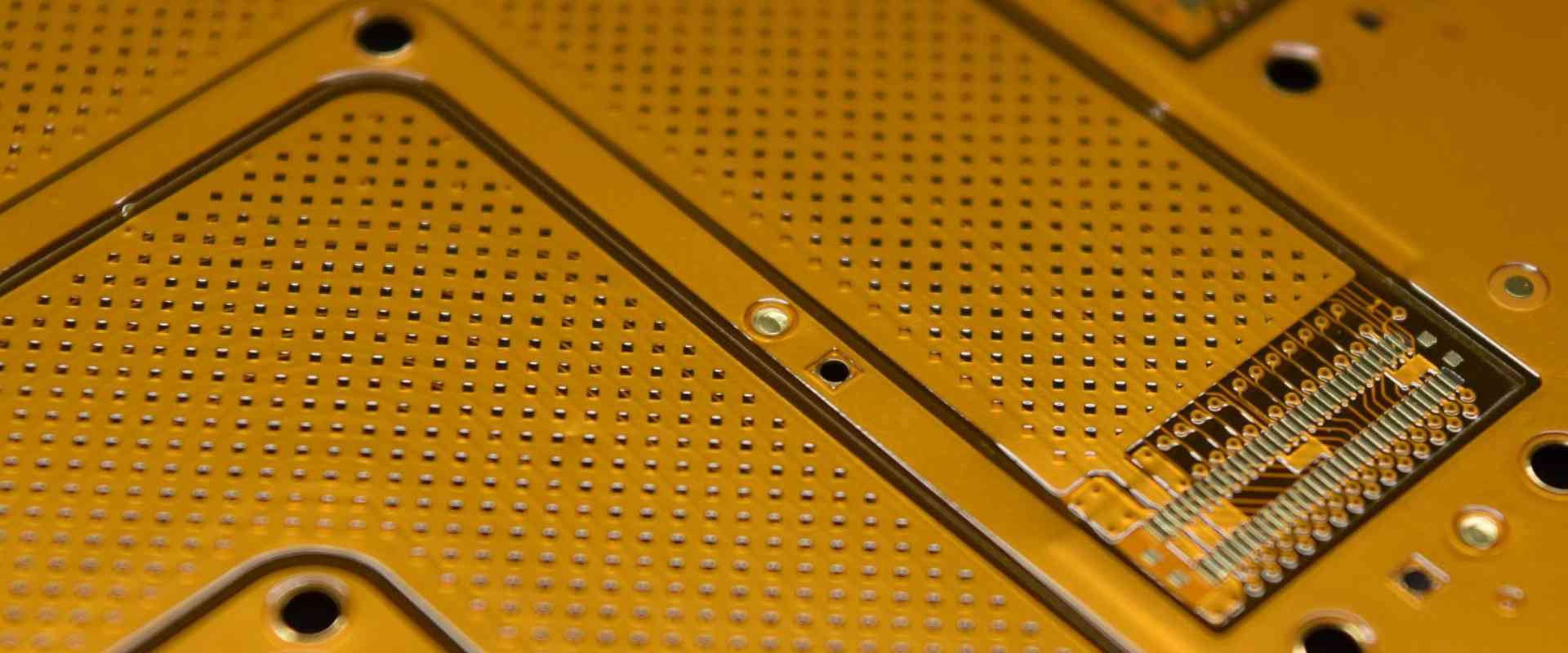
A flex circuit board is a PCB made from flexible insulating substrate materials like polyimide or polyester. Instead of the rigid laminate materials used in rigid PCBs, the flexible base layers allow the board to bend and flex repeatedly without damage. The conductive pathways are photolithographically etched or printed in copper foil laminated onto the flexible substrate. Components can be directly soldered or glued onto the surface or housed in the flexible material itself.
Typical cross-section of a flex PCB board. Image source: ResearchGate
Compared to rigid boards, flex circuits provide:
- Increased flexibility and bend radius
- Improved shock and vibration resistance
- Reduced weight and size
- Higher component density
- Dynamic flexing during use
- 3D assembly and installation
Common applications of flex circuits include consumer electronics, automotive systems, aerospace, medical devices, industrial systems, and wearables.
Benefits of Using Flex Circuits
There are several key benefits that make flex PCBs an attractive choice compared to rigid PCBs:
Flexibility – The flexible substrate material allows the circuit board to bend and conform to a variety of shapes and surfaces. This enables flex circuits to fit into tight, curved, or dynamic spaces.
Durability – Flex circuits are highly durable against shaking, twisting, and repeated bending. The boards can flex without damage to traces or solder joints. This makes them suitable for medical, military, aerospace applications.
Lightweight – With a thin, flexible substrate instead of a thick, rigid laminate, flex circuits have a much lower weight. This lightweight nature allows for greater portability of devices.
Thin and compact design – A flex circuit’s thin profile, often less than 0.15mm, allows for tight folds and stacked assemblies. This leads to space and weight savings in product designs.
Higher component density – Smaller spaces between traces enables higher component densities compared to rigid boards. More components can fit into a smaller surface area.
Simplified assemblies – Flex circuits allow for flexible 3D assemblies and installations that simplify electronic interconnections. Multiple rigid PCBs can be replaced by a single flex circuit.
Dynamic flexing – The flex circuits can dynamically flex during use for things like connectors, modems, and wearable devices. Rigid PCBs are unable to withstand continuous flexing.
Cost savings – The simplified designs, assemblies, and lower material use can result in cost savings compared to using multiple rigid PCBs. However, flex PCB setup costs are higher.
Typical Design and Layout
When designing a flex circuit board, engineers follow a layout optimized for flexibility while ensuring electrical connectivity reliability. Here are some key flex circuit design considerations:
- Stackup – The board stackup refers to the layering of the flexible substrate, adhesive, and copper foil. Common options are single-sided, double-sided, multilayer, rigid-flex, and sculpted flex stacks.
- Bend zones – Sections of the board meant for bending or folding should be designed as bend zones with no components. Reinforcement material can be added for bend durability.
- Trace routing – Traces in bend zones require specialized routing to prevent damage like cracking. Strategies include using curved traces, removing acute angles, and cross-hatching wide traces.
- Stiffener integration – Rigid stiffeners made from FR4 or polyimide substrates are added to protect components, prevent flexing, and ease handling and assembly.
- Vias and holes – Vias and component holes require conductive coating and sufficient anchoring to avoid cracking around the edges during bending.
- Adhesives – Choosing the right adhesive is critical to ensure lamination strength for flexing without damaging traces or pads. Common choices are acrylic, epoxy, or polyimide adhesives.
- Components – Smaller surface mount devices are most reliable. Proper strain relief design is needed to prevent component or solder joint damage during flexing.
- Conformal coatings – Protective acrylic or urethane conformal coatings can be applied to provide extra moisture, chemical, abrasion, and vibration resistance.
Flex Circuit Manufacturing Process

Professional flex PCB manufacturers follow specialized processes tuned specifically for high quality flex circuits. Here is a general overview of the flex circuit fabrication process:
1. Design – The circuit layout is designed and simulated using CAD software like Altium, KiCad, or Cadence Allegro. The critical elements like stackup, traces, stiffeners, and bend zones are defined.
2. CAM and Gerber Files – The CAD data is converted into CAM fabrication data like Gerber and drill files. This data defines the individual conductive and insulating layers.
3. Materials Preparation – The flexible substrate material sheets, coverlay/bondply layers, and copper foils are prepared. The material thickness and copper weights are selected based on the design.
4. Imaging – Using lithographic processes like photoexposure, the circuit traces are imaged onto the copper layers as an etch-resistant pattern.
5. Etching – The exposed copper is chemically etched away, leaving only the desired circuit trace pattern on the base substrate.
6. Component Assembly – Components are carefully assembled onto the PCB surface using soldering, conductive epoxy, or other methods.
7. Bonding – Multiple flexible layers are bonded using heat-activated adhesives like acrylic or polyimide. Alignment is critical.
8. Via Drilling – Mechanical or laser drills create holes that form the conductive interconnections or vias between layers.
9. Via Metallization – The drilled vias are plated with copper to form the conductive walls connecting traces on different layers.
10. Stiffener Attachment – If used, stiffeners made of rigid PCB substrates are added using bonding sheets.
11. Quality Testing – Electrical tests validate connectivity, continuity, and isolation. Mechanical tests check bend tolerance and component adhesion.
12. Finishing – Final finishes like solder masking, legends, hole plugs/fills, and conformal coating are applied as needed.
The complexity of the flex PCB fabrication process underscores the benefits of partnering with a qualified, experienced flex circuit manufacturer. Their expertise in flex materials, specialized equipment, process tuning, and quality control helps deliver reliable, high-performing flex boards.
Common Applications of Flexible PCBs
Thanks to their unique benefits, flex circuits are the ideal solution for electronics that require bending, flexing, rolling, folding and/or vibration resistance. Here are some of the most common applications:
Consumer Electronics
- Mobile phones
- Laptop and tablet displays
- Printer controllers
- VR headsets
- Wearable devices
Automotive
- Instrument panels
- Engine control units
- Airbag sensors
- GPS antennas
Medical
- Hearing aids
- Pacemakers
- Ultrasound transducers
- Patient monitoring systems
Industrial
- Robotics
- Touch screens
- Control panels
- Optical imaging systems
Military/Aerospace
- Guidance systems
- Avionics
- Radars
- Satellite systems
Other
- Cameras
- Connectors and cables
- LED lighting
- Liquid crystal displays
Flex circuits enable small, lightweight, and durable electronics designs across nearly every industry and application where flexibility, space savings, or reliability are important requirements.
Frequently Asked Questions
Q: How is a flex PCB different from a rigid PCB?
A: The main difference is that rigid PCBs use stiff, laminated substrates like FR4, while flex PCBs use thin, bendable substrates like polyimide. This allows flex circuits to dynamically bend and conform without damage.
Q: Can components be mounted directly onto flex PCBs?
A: Yes, but small surface mount devices are preferred. Proper strain relief design is needed to prevent damage during flexing. Some components can also be embedded into cutouts in the flexible substrate.
Q: What are some key considerations when designing flex circuits?
A: Critical aspects are stackup, trace routing, bend zones, stiffeners, vias/holes, adhesives, components, and conformal coatings. The design must balance electrical connectivity with mechanical flexibility and durability.
Q: What are some typical substrates used in flex PCBs?
A: Common flexible substrate films include polyimide, polyester (PET), polyethylene naphthalate (PEN), and fluorinated ethylene propylene (FEP). Polyimide films like Kapton are widely used.
Q: How many bend cycles can flex circuits withstand?
A: Properly designed flex PCBs can reliably withstand millions of dynamic bend cycles for applications like opening/closing laptop lids. This depends on several design factors.
Q: What are some methods for assembling components onto flex PCBs?
A: Common assembly techniques include soldering, conductive epoxy, mechanical assembly, thermocompression bonding, ultrasonic welding, and laser welding. Surface mount devices are most reliable.
Q: Are flex PCBs more expensive than rigid PCBs?
A: Generally yes, on a per unit basis for small quantities. But they can provide cost savings at high volumes by enabling simpler, lighter assemblies vs. using multiple rigid boards and connectors.
Conclusion
Flex PCBs provide invaluable benefits like flexibility, durability, and space savings for electronics in demanding applications. Careful design consideration and specialized manufacturing processes enable reliable dynamic bending performance. With an understanding of their capabilities, benefits, and tradeoffs, flex circuits can be a versatile solution for enabling the compact, lightweight, and robust electronic devices of the future. They empower electrical engineers and product designers with new possibilities for innovation.


Leave a Reply