Introduction to Flex-Rigid PCBs
Flex-rigid PCBs are a unique combination of flexible and rigid printed circuit boards that offer the best of both worlds. These hybrid PCBs consist of both flexible and rigid substrates, allowing for greater design flexibility, improved reliability, and reduced overall size and weight of electronic devices. Flex-rigid PCBs have become increasingly popular in various industries, including aerospace, automotive, medical, and consumer electronics, due to their ability to meet the demanding requirements of modern electronic applications.
What are Flex-Rigid PCBs?
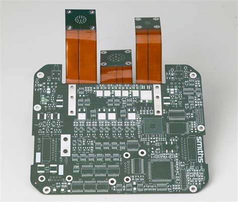
Flex-rigid PCBs are a type of printed circuit board that combines flexible and rigid substrates into a single, integrated unit. The flexible portions of the board are typically made from polyimide or other flexible materials, while the rigid portions are made from standard FR-4 or other rigid substrates. The flexible and rigid sections are interconnected using plated through-holes (PTHs) or other methods, allowing for electrical continuity throughout the board.
Advantages of Flex-Rigid PCBs
Flex-rigid PCBs offer several advantages over traditional rigid PCBs, including:
-
Increased design flexibility: Flex-rigid PCBs allow for more complex and compact designs, as the flexible portions can be folded, bent, or twisted to fit into tight spaces or conform to unique shapes.
-
Improved reliability: By eliminating the need for connectors and cables between rigid PCBs, flex-rigid PCBs reduce the potential for connection failures and improve overall system reliability.
-
Reduced size and weight: Flex-rigid PCBs enable the creation of smaller and lighter electronic devices, as they can replace multiple rigid PCBs and the associated connectors and cables.
-
Enhanced signal integrity: The shorter signal paths and reduced number of interconnects in flex-rigid PCBs can improve signal integrity and reduce electromagnetic interference (EMI).
-
Cost-effective: Although the initial cost of flex-rigid PCBs may be higher than traditional rigid PCBs, the overall system cost can be lower due to reduced assembly time, fewer components, and improved reliability.
Flex-Rigid PCB Manufacturing Process
The manufacturing process for flex-rigid PCBs is more complex than that of standard rigid PCBs, as it involves the integration of both flexible and rigid substrates. The following steps outline the general flex-rigid PCB manufacturing process:
1. Design and Preparation
The first step in manufacturing flex-rigid PCBs is to create a detailed design that specifies the layout, layer stackup, and materials to be used. The design must take into account the unique requirements of flex-rigid PCBs, such as bend radii, stiffener placement, and coverlay application. Once the design is finalized, the data is prepared for manufacturing, including the generation of Gerber files, drill files, and other necessary documentation.
2. Material Selection
Selecting the appropriate materials for flex-rigid PCBs is crucial to ensure the desired performance and reliability. The most common materials used for the flexible portions of the board are polyimide films, such as DuPont™ Pyralux® or Rogers ULTRALAM®. These materials offer excellent flexibility, thermal stability, and electrical properties. For the rigid portions of the board, standard FR-4 or high-performance materials like Rogers RO4000® series can be used, depending on the application requirements.
3. Fabrication of Flexible and Rigid Substrates
The flexible and rigid substrates are fabricated separately using different processes. For the flexible substrates, the process typically involves:
a. Laminating the polyimide film to a copper foil using adhesive or adhesiveless methods.
b. Patterning and etching the copper to create the desired Circuit Traces.
c. Applying a coverlay or soldermask to protect the circuits and define the solderable areas.
For the rigid substrates, the process is similar to standard PCB fabrication, which includes:
a. Laminating the copper foil to the rigid substrate material.
b. Drilling holes for vias and component mounting.
c. Patterning and etching the copper to create the circuit traces.
d. Applying soldermask and silkscreen for protection and component identification.
4. Lamination and Bonding
Once the flexible and rigid substrates are fabricated, they are laminated together using a combination of heat and pressure. The adhesive used for lamination must be compatible with both the flexible and rigid materials and provide good adhesion and thermal stability. The lamination process typically involves:
a. Aligning the flexible and rigid substrates according to the design.
b. Applying the adhesive between the substrates.
c. Pressing the substrates together under controlled temperature and pressure conditions.
d. Curing the adhesive to ensure a strong, reliable bond.
5. Drilling and Plating
After lamination, holes are drilled through the combined flex-rigid stack to create vias and mounting holes for components. The holes are then plated with copper to provide electrical continuity between the layers and to the surface of the board. The plating process typically involves:
a. Cleaning and conditioning the hole walls to ensure good adhesion.
b. Applying a thin layer of electroless copper to provide a conductive base for electroplating.
c. Electroplating additional copper to achieve the desired thickness and conductivity.
6. Surface Finishing
The final step in the flex-rigid PCB manufacturing process is to apply a surface finish to the exposed copper areas to protect them from oxidation and enhance solderability. Common surface finishes for flex-rigid PCBs include:
a. Hot Air Solder Leveling (HASL): A tin-lead or lead-free solder is applied to the copper surfaces and then leveled using hot air.
b. Electroless Nickel Immersion Gold (ENIG): A layer of nickel is applied to the copper, followed by a thin layer of gold to provide excellent solderability and shelf life.
c. Immersion Silver (IAg): A thin layer of silver is applied to the copper, providing good solderability and lower cost compared to ENIG.

Designing Flex-Rigid PCBs
Designing flex-rigid PCBs requires careful consideration of several factors to ensure optimal performance, reliability, and manufacturability. Some key design guidelines for flex-rigid PCBs include:
1. Bend Radius
The bend radius is a critical factor in flex-rigid PCB design, as it determines the minimum allowed radius for the flexible portions of the board without causing damage or compromising reliability. The bend radius depends on the thickness and material properties of the flexible substrate, as well as the number and location of copper traces. As a general rule, the minimum bend radius should be at least six times the total thickness of the flexible substrate.
2. Stiffener Placement
Stiffeners are used in flex-rigid PCBs to provide support and stability to the flexible portions of the board, especially in areas where components are mounted or where the board is subject to mechanical stress. Stiffeners are typically made from rigid materials such as FR-4 or polyimide and are laminated to the flexible substrate. When placing stiffeners, designers should consider:
a. Leaving enough space between the stiffener and the bend area to allow for proper flexing.
b. Ensuring that the stiffener does not interfere with the placement of components or the routing of traces.
c. Using multiple smaller stiffeners instead of a single large one to provide more localized support and flexibility.
3. Coverlay Application
Coverlay is a protective layer applied to the flexible portions of the board to insulate and protect the copper traces. When designing flex-rigid PCBs, it is important to consider the placement and size of the coverlay openings to ensure proper access to solderable areas and to avoid interference with the bending of the board. Designers should also specify the type and thickness of the coverlay material based on the application requirements, such as chemical resistance, thermal stability, and flexibility.
4. Layer Stackup
The layer stackup of a flex-rigid PCB is a critical design element that determines the electrical performance, mechanical properties, and manufacturability of the board. When designing the layer stackup, consider:
a. The number and arrangement of flexible and rigid layers based on the circuit requirements and mechanical constraints.
b. The thickness and material properties of each layer, including the copper weight, dielectric constant, and loss tangent.
c. The use of shielding layers or ground planes to reduce EMI and improve signal integrity.
d. The placement of signal, power, and ground layers to minimize crosstalk and ensure proper power distribution.
5. Via Design
Vias are used in flex-rigid PCBs to provide electrical connections between layers and to the surface of the board. When designing vias for flex-rigid PCBs, consider:
a. The size and location of the vias based on the circuit requirements and the mechanical constraints of the board.
b. The use of microvias or blind vias to minimize the impact on the flexible portions of the board and to improve signal integrity.
c. The via-in-pad design to reduce the overall size of the board and improve the routing density.
d. The use of filled or capped vias to improve the mechanical strength and reliability of the board.

Applications of Flex-Rigid PCBs
Flex-rigid PCBs are used in a wide range of applications across various industries, where their unique combination of flexibility, reliability, and performance is required. Some common applications of flex-rigid PCBs include:
1. Aerospace and Defense
In aerospace and defense applications, flex-rigid PCBs are used in avionics systems, satellite communications, and military equipment where high reliability, resistance to vibration and shock, and the ability to operate in harsh environments are critical. Flex-rigid PCBs enable the creation of compact, lightweight, and rugged electronic assemblies that can withstand the rigors of aerospace and defense applications.
2. Automotive
Flex-rigid PCBs are increasingly used in automotive applications, such as engine control modules, infotainment systems, and advanced driver assistance systems (ADAS). The ability of flex-rigid PCBs to conform to complex shapes and fit into tight spaces makes them ideal for the space-constrained environment of modern vehicles. Additionally, the improved reliability and reduced weight of flex-rigid PCBs contribute to the overall performance and efficiency of automotive electronics.
3. Medical Devices
Medical devices, such as wearable monitors, implantable devices, and diagnostic equipment, often require the use of flex-rigid PCBs to achieve the necessary form factor, reliability, and biocompatibility. Flex-rigid PCBs allow for the creation of compact, lightweight, and conformable devices that can be worn or implanted in the body without causing discomfort or irritation. The ability to withstand repeated flexing and the use of biocompatible materials make flex-rigid PCBs well-suited for medical applications.
4. Consumer Electronics
Flex-rigid PCBs are widely used in consumer electronics, such as smartphones, tablets, laptops, and wearables, where the demand for smaller, lighter, and more feature-rich devices is driving the need for advanced packaging solutions. Flex-rigid PCBs enable the creation of thin, compact, and reliable electronic assemblies that can fit into the slim profiles of modern consumer devices. The ability to integrate multiple functions into a single flex-rigid assembly also helps to reduce the overall size and cost of consumer electronics.
5. Industrial Automation
In industrial automation applications, flex-rigid PCBs are used in sensors, controllers, and communication modules where the ability to operate in harsh environments and withstand frequent flexing is essential. Flex-rigid PCBs offer improved reliability and resistance to vibration, shock, and temperature extremes compared to traditional rigid PCBs. The use of flex-rigid PCBs in industrial automation helps to improve the efficiency, reliability, and longevity of automated systems and equipment.

RAYPCB’s Capabilities in Flex-Rigid PCB Manufacturing
RAYPCB is a leading manufacturer of high-quality flex-rigid PCBs, offering a full range of services from design and prototyping to volume production. With state-of-the-art facilities, experienced engineers, and a commitment to quality and customer satisfaction, RAYPCB is well-positioned to meet the diverse needs of customers across various industries.
1. Advanced Manufacturing Equipment
RAYPCB has invested in advanced manufacturing equipment and technology to ensure the highest quality and reliability of its flex-rigid PCBs. This includes:
a. High-precision laser drilling and routing machines for accurate and efficient hole formation and board shaping.
b. Advanced lamination presses for ensuring strong, reliable bonding between flexible and rigid substrates.
c. Automated optical inspection (AOI) and X-ray inspection systems for detecting and preventing defects.
d. State-of-the-art plating and surface finishing equipment for achieving the desired electrical and mechanical properties.
2. Experienced Engineering Team
RAYPCB’s team of experienced engineers and PCB design experts works closely with customers to optimize their flex-rigid PCB designs for manufacturability, reliability, and performance. The team provides valuable guidance and support throughout the design and manufacturing process, helping customers to navigate the complexities of flex-rigid PCB technology and achieve their project goals.
3. Strict Quality Control
RAYPCB maintains a strict quality control system to ensure that every flex-rigid PCB meets the highest standards of quality and reliability. This includes:
a. Thorough incoming inspection of raw materials to ensure consistency and compliance with specifications.
b. In-process inspection and testing at critical stages of the manufacturing process to identify and correct any issues.
c. Final inspection and functional testing of finished products to verify conformance to customer requirements and industry standards.
d. Continuous improvement of processes and procedures based on customer feedback and industry best practices.
4. Rapid Prototyping and Volume Production
RAYPCB offers both rapid prototyping and volume production services for flex-rigid PCBs, enabling customers to quickly validate their designs and ramp up to full-scale production. The company’s flexible manufacturing capabilities and strong supply chain partnerships allow it to meet tight deadlines and accommodate varying order quantities without compromising quality or reliability.
5. Customization and Value-Added Services
In addition to standard flex-rigid PCB manufacturing services, RAYPCB offers a range of customization and value-added services to meet the unique needs of its customers. This includes:
a. Custom material selection and stackup design to optimize the performance and reliability of the flex-rigid PCB.
b. Embedded component integration to further reduce the size and complexity of the assembly.
c. Controlled impedance routing and signal integrity analysis to ensure optimal electrical performance.
d. Assembly and testing services, including component sourcing, SMT Assembly, and functional testing.
Frequently Asked Questions (FAQ)
1. What is the typical lead time for flex-rigid PCB Prototypes at RAYPCB?
RAYPCB offers rapid prototyping services for flex-rigid PCBs, with typical lead times of 7-14 days, depending on the complexity of the design and the materials required. For more accurate lead time estimates, customers can contact RAYPCB’s sales team with their specific project requirements.
2. What are the minimum and maximum layer counts for flex-rigid PCBs at RAYPCB?
RAYPCB can manufacture flex-rigid PCBs with layer counts ranging from 4 to 28 layers, including both flexible and rigid layers. The specific layer count and stackup design will depend on the customer’s application requirements and design constraints.
3. What types of surface finishes does RAYPCB offer for flex-rigid PCBs?
RAYPCB offers a variety of surface finishes for flex-rigid PCBs, including HASL, ENIG, and IAg. The choice of surface finish will depend on the customer’s soldering requirements, environmental conditions, and cost considerations. RAYPCB’s engineering team can provide guidance on selecting the most appropriate surface finish for a given application.
4. Can RAYPCB provide assembly services for flex-rigid PCBs?
Yes, RAYPCB offers assembly services for flex-rigid PCBs, including component sourcing, SMT assembly, and functional testing. Customers can leverage RAYPCB’s expertise and capabilities to streamline their supply chain and ensure the quality and reliability of their final product.
5. What certifications and quality standards does RAYPCB maintain for flex-rigid PCB manufacturing?
RAYPCB maintains a number of certifications and quality standards to ensure the highest level of quality and reliability for its flex-rigid PCBs. These include ISO 9001:2015 for quality management, ISO 14001:2015 for environmental management, and IATF 16949:2016 for automotive quality management. RAYPCB also complies with industry standards such as IPC-6013 for flex and Rigid-flex PCBs and IPC-A-600 for PCB acceptability.
Conclusion
Flex-rigid PCBs offer a unique combination of flexibility, reliability, and performance that makes them ideal for a wide range of applications across various industries. By combining the best attributes of flexible and rigid substrates, flex-rigid PCBs enable the creation of compact, lightweight, and robust electronic assemblies that can withstand the rigors of modern electronic applications.
RAYPCB is a trusted partner for flex-rigid PCB manufacturing, offering advanced capabilities, experienced engineers, and a commitment to quality and customer satisfaction. With its state-of-the-art facilities, strict quality control, and range of customization and value-added services, RAYPCB is well-positioned to meet the diverse needs of customers across industries and help them bring their innovative products to market quickly and efficiently.
As the demand for smaller, lighter, and more reliable electronic devices continues to grow, the importance of flex-rigid PCB technology will only continue to increase. By staying at the forefront of this technology and continuously investing in its capabilities and expertise, RAYPC


Leave a Reply