Introduction to Rigid-flex PCBs
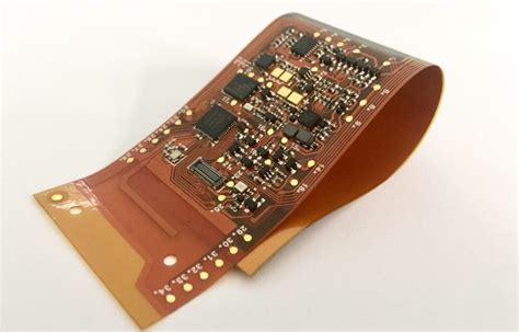
Rigid-flex PCBs are a type of printed circuit board that combines both rigid and flexible substrates into a single board. This unique design allows for greater flexibility and durability in electronic devices, making them ideal for applications that require compact packaging or exposure to harsh environments. Rigid-flex PCBs have become increasingly popular in recent years due to their ability to reduce weight, save space, and improve reliability.
Advantages of Rigid-flex PCBs
- Space-saving design
- Reduced weight
- Improved reliability
- Enhanced flexibility
- Reduced assembly time and costs
Understanding the Basics of Rigid-flex PCB Design
Rigid-flex PCB Structure
A rigid-flex PCB consists of three main components:
- Rigid layers: These are the standard FR-4 or other rigid PCB materials that provide structural support and house the majority of the electronic components.
- Flexible layers: These are thin, flexible substrates, typically made of polyimide, that allow the PCB to bend and flex as needed.
- Adhesive layers: These layers bond the rigid and flexible sections together, ensuring a secure and reliable connection.
Designing for Flexibility
When designing a rigid-flex PCB, it’s essential to consider the flexibility requirements of the application. This involves determining the number of flexible layers needed, the bend radius, and the overall thickness of the flexible sections.
| Bend Radius | Minimum Thickness (mm) | Maximum Thickness (mm) |
|---|---|---|
| 1x | 0.05 | 0.15 |
| 2x | 0.10 | 0.30 |
| 3x | 0.15 | 0.45 |

Advanced Techniques for Rapid Rigid-flex PCB Design
3D Modeling and Simulation
Using 3D modeling software to create a virtual representation of your rigid-flex PCB can help you visualize the final product and identify potential design issues before manufacturing begins. This can save time and reduce the need for costly revisions.
Design for Manufacturing (DFM)
When designing a rigid-flex PCB, it’s crucial to consider the manufacturing process and adhere to DFM guidelines. This includes:
- Ensuring adequate clearance between components
- Avoiding sharp bends in the flexible sections
- Using appropriate materials and layer stackups
- Providing clear and accurate manufacturing files
Optimizing Signal Integrity
Signal integrity is a critical concern in rigid-flex PCB design, particularly in high-speed applications. To optimize signal integrity, consider the following:
- Use controlled impedance design techniques
- Minimize crosstalk and electromagnetic interference (EMI)
- Implement proper grounding and shielding
- Use appropriate termination and matching networks

Best Practices for Rigid-flex PCB Design
- Start with a clear understanding of the application requirements
- Use a modular design approach to simplify complex layouts
- Collaborate closely with your manufacturing partner
- Perform thorough testing and validation before finalizing the design
- Document the design process and maintain accurate records

Frequently Asked Questions (FAQ)
1. What is the main difference between rigid and rigid-flex PCBs?
Rigid PCBs are made entirely of rigid substrates, while rigid-flex PCBs combine both rigid and flexible substrates into a single board. This allows rigid-flex PCBs to bend and flex as needed, making them suitable for applications that require compact packaging or exposure to harsh environments.
2. What are the most common applications for rigid-flex PCBs?
Rigid-flex PCBs are commonly used in:
- Medical devices
- Aerospace and defense equipment
- Automotive electronics
- Wearable technology
- Industrial automation systems
3. What materials are used in rigid-flex PCBs?
Rigid-flex PCBs typically use FR-4 or other rigid PCB materials for the rigid sections and polyimide for the flexible sections. Adhesive layers, such as acrylic or epoxy, are used to bond the rigid and flexible sections together.
4. How do I choose the right bend radius for my rigid-flex PCB?
The bend radius of a rigid-flex PCB depends on the thickness of the flexible sections and the flexibility requirements of the application. As a general rule, the bend radius should be at least 10 times the thickness of the flexible layers to minimize stress and prevent damage.
5. What are some common challenges in rigid-flex PCB design?
Some common challenges in rigid-flex PCB design include:
- Ensuring proper alignment between rigid and flexible sections
- Maintaining signal integrity in high-speed applications
- Minimizing stress and strain on the flexible sections
- Adhering to DFM guidelines and manufacturing constraints
- Achieving reliable and consistent performance over the product lifecycle
Conclusion
Rigid-flex PCBs offer numerous advantages over traditional rigid PCBs, including space savings, reduced weight, improved reliability, and enhanced flexibility. However, designing rigid-flex PCBs requires a thorough understanding of the unique requirements and challenges associated with this technology.
By mastering advanced techniques such as 3D modeling, DFM, and signal integrity optimization, and following best practices for design and collaboration, engineers can create robust and reliable rigid-flex PCBs that meet the demands of today’s complex electronic devices. With the right skills and knowledge, rapid design of rigid-flex PCBs is achievable, leading to faster time-to-market and improved product performance.


Leave a Reply