Introduction
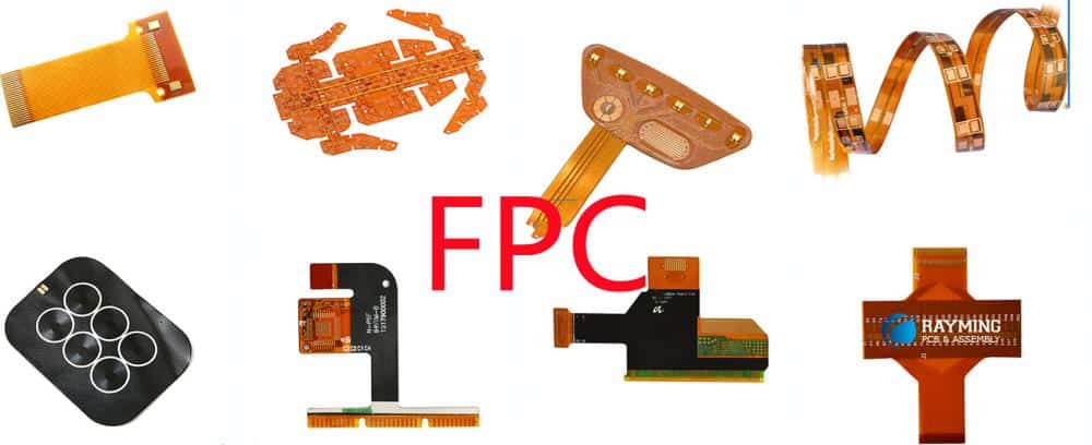
Flex circuits, also known as flexible printed circuits (FPCs), and rigid flex circuits are two common types of printed circuit boards (PCBs) used in electronics manufacturing. While they share some similarities, there are important differences between flex and rigid flex circuits in terms of their construction, applications, and benefits.
Overview of flex circuits
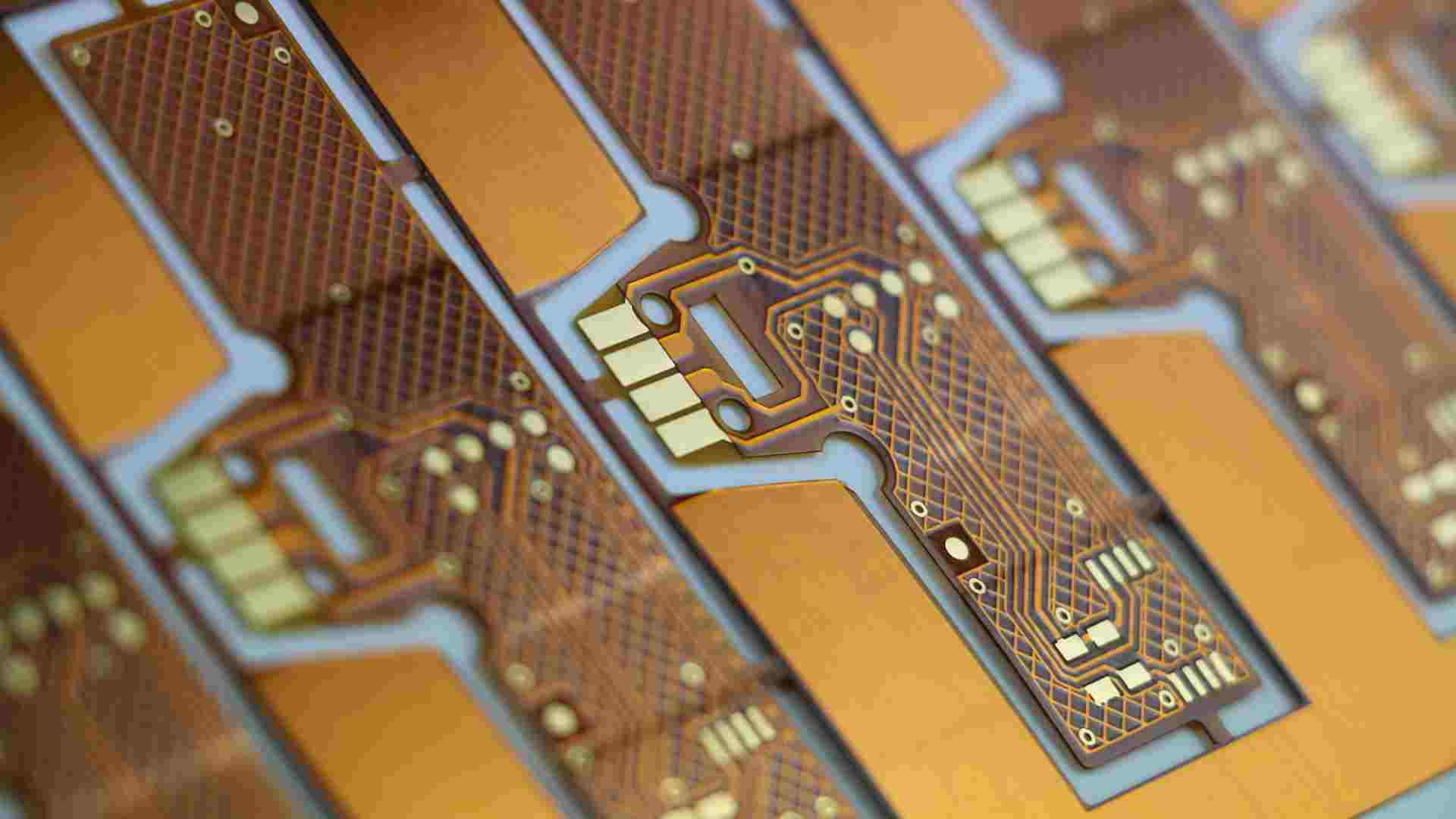
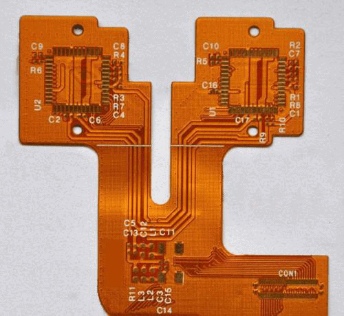
A flex circuit is a thin, lightweight PCB that can bend and flex. It is made of a flexible polymer base layer, such as polyimide or polyester, that is layered with conductive copper traces and components. The lack of rigidity allows flex circuits to be dynamically flexed and contorted to fit into tight spaces and movable assemblies.
Flex circuits provide several advantages over traditional rigid PCBs:
- Extremely lightweight and thin profile
- Can conform to 3D surfaces and dynamic contours
- Allow for motion/vibration within an assembly
- Enables compact, space-efficient designs
- Fewer interconnects than wires/cables
Common applications of flex circuits include consumer electronics, medical devices, automotive, and industrial equipment. For example, flex circuits are often used for interconnectivity in foldable/rollable displays, wearables, printers, cameras, and more.
Overview of rigid flex circuits
Rigid flex circuits, as the name suggests, contain both rigid and flexible substrates joined together. Essentially they incorporate flex circuitry with sections of a traditional, rigid FR-4 PCB.
The rigid sections provide:
- Structure/frame for mounting components
- Stability and protection of components
- Ease of assembly/mounting
While the flexible sections allow:
- Dynamic flexing and 3D assembly
- Motion/vibration dampening
- Compact, space-saving interconnections
By combining rigid and flex materials, rigid flex circuits deliver ideal mechanical and electrical properties where needed. The rigid sections also eliminate the need for connectors between separate PCBs.
Rigid flex circuits are commonly used in aerospace, defense, telecom, medical, and consumer electronics where reliability and high-performance are critical.
Key Differences Between Flex Circuits and Rigid Flex
While flex circuits and rigid flex share some traits, there are several key differences between the two technologies:
Construction
- Flex circuits consist solely of a flexible dielectric base material (like polyimide) with conductive copper traces. No rigid sections.
- Rigid flex circuits contain both rigid board material (like FR-4) and flexible dielectric material joined together. Provides both rigid and dynamic flex regions.
Components
- Flex circuits have very limited component mounting directly on the flexible material. Mainly for simple devices like resistors and capacitors. Not suitable for most rigid components or connectors.
- Rigid flex circuits allow mounting of virtually any component, connector or stiffener on the rigid PCB sections. Maximizes component density.
Layer Count
- Flex circuits typically 1-2 conductive layers. Occasionally 2-4 layers but more complex flex circuits are rare.
- Rigid flex circuits range from 2 layers to 20+ layers on the rigid sections, allowing for complex high density designs.
Interconnects
- Flex circuits rely on external wiring, cables or connectors to interface with other PCBs and components.
- Rigid flex circuits can eliminate external connections by integrating multiple PCBs/components through flexible junctions.
Bend Radius
- Flex circuits can bend to a tight radius, often down to 10x the circuit thickness depending on construction. Dynamic flexing down to 0.5″.
- Rigid flex circuits have a larger minimum bend radius, around 1-2″ typically, limited by the rigid sections.
Applications
- Flex circuits used when simplicity, thinness, light weight and dynamic contours are critical. Consumer electronics, medical, industrial.
- Rigid flex circuits selected for reliability, ruggedness, complex interconnects. Defense, aerospace, automation, instrumention.
Pros and Cons Comparison
Flex Circuits
Advantages:
- Extremely lightweight and thin
- Can conform to dynamic 3D profiles
- Allows for continuous motion/vibration
- Compact, space efficient interconnections
- Simpler design/assembly vs. rigid flex
Disadvantages:
- Limited in component mounting options
- Requires external wiring or connectors
- Less rugged and durable than rigid PCBs
- Lower layer counts restricts design complexity
- Not suitable for high density component mounting
Rigid Flex Circuits
Advantages:
- Combines rigid and flex properties
- Allows mounting of virtually any component
- Eliminates need for connectors/cables
- Withstands vibration, shock, temperature cycling
- High layer counts supports complex, dense designs
- Rugged and durable construction
Disadvantages:
- Thicker and heavier than pure flex circuits
- Requires careful design for reliable flex-to-rigid transitions
- Capturing flex areas can be challenging
- Often higher cost than flex or rigid-only PCBs
Typical Applications
Flex Circuit Applications
- Consumer electronics (smartphones, wearables, displays)
- Automotive sensors and control circuits
- Medical devices and surgical tools
- Industrial machine and robot interconnects
- Printers and imaging equipment
Rigid Flex Applications
- Aerospace and defense systems
- Telecommunications infrastructure
- Medical equipment
- Industrial robotics and automation
- Test and measurement instrumentation
- High-performance computing hardware
Fabrication and Design Considerations
Successfully implementing flex and rigid flex circuits requires attention to layout, materials selection and manufacturing processes. Here are some key considerations:
Circuit Layout
- Avoid sharp corners and angles in flexing areas
- Provide proper clearances for dynamic flexing
- Minimize unsupported spans in flexible regions
- Strategically place and isolate rigid sections
Materials
- Compatible coefficients of thermal expansion
- Proper flexible dielectric and adhesive materials
- Considerations for impedance, loss, etc.
- High Tg materials for maximizing bend cycles
Fabrication
- Precise control of etching and imaging
- Thin dielectrics and trace sizes
- Advanced filling and plating processes
- Careful lamination of stiffeners and rigid layers
- Robust QA to ensure flex integrity
By partnering with an experienced rigid flex manufacturer, optimal designs can be achieved.
Frequently Asked Questions
What are the key benefits of using a rigid flex circuit?
The primary benefits of rigid flex circuits are the abilities to:
- Eliminate connectors and cables through integrated flexing interconnections
- Mount components and achieve high density on rigid sections
- Withstand vibration, shock, and temperature cycling in harsh environments
- Enable designs that require dynamic and static sections
- Achieve complex circuitry through high layer counts (up to 20+ layers)
Are rigid flex circuits compatible with SMT assembly?
Yes, the rigid portions of a rigid flex circuit board utilize standard FR-4 materials and constructions that are fully compatible with surface mount assembly processes, including reflow soldering, cleaning, AOI etc.
Can conformal coating be applied to rigid flex circuits?
Conformal coating can be applied to rigid flex circuits, however it may restrict or impede flexibility in the flexing areas depending on material used and thickness. Advanced selective coating processes are often used. Stress relief features in the design are also beneficial.
What are some examples of rigid flex circuit applications?
Common rigid flex applications include:
- Defense and aerospace avionics
- Satellite communication systems
- Medical imaging equipment
- Industrial robotics and automation
- Test and measurement instruments
- High-end consumer electronics
Any application requiring compact, reliable interconnects between static and dynamic PCBs can benefit from rigid flex circuits.
How many bend cycles can a rigid flex circuit withstand?
Rigid flex circuits are typically designed for hundreds of bend cycles. With proper design and material selection such as high Tg flexible dielectrics, rigid flex circuits can endure thousands and even millions of dynamic flexing cycles for long term reliability.


Leave a Reply