What is an OLED Display?
Before diving into the specifics of the SSD1306, let’s briefly discuss OLED displays. OLED displays are a type of flat panel display technology that uses organic compounds to emit light when an electric current is applied. Compared to traditional LCD (Liquid Crystal Display) technology, OLED displays offer several advantages:
- Self-illuminating pixels: Each pixel in an OLED display emits its own light, eliminating the need for a backlight.
- High contrast ratio: OLED displays can achieve deep blacks by completely turning off individual pixels, resulting in a high contrast ratio.
- Wide viewing angles: OLED displays maintain consistent color and brightness across wide viewing angles.
- Thin and lightweight: Without the need for a backlight, OLED displays can be made thinner and lighter than LCDs.
- Fast response times: OLED displays have faster response times, reducing motion blur and making them suitable for video and animation.
Introduction to the SSD1306
The SSD1306 is a single-chip CMOS OLED/PLED driver with a controller for organic/polymer light-emitting diode dot-matrix graphic display systems. It is designed for common OLED displays with resolutions of 128×64 pixels and supports both I2C and SPI communication interfaces.
Key Features of the SSD1306
-
Resolution: The SSD1306 supports a display resolution of 128×64 pixels, which is sufficient for displaying text, simple graphics, and small images.
-
Communication Interfaces: The chip offers two communication interface options:
- I2C (Inter-Integrated Circuit): A two-wire serial communication protocol that requires only two lines (SDA for data and SCL for clock) in addition to power and ground.
-
SPI (Serial Peripheral Interface): A four-wire serial communication protocol that offers higher data transfer speeds compared to I2C. It requires four lines (MOSI for data, SCK for clock, CS for chip select, and DC for data/command) in addition to power and ground.
-
Contrast Control: The SSD1306 allows for adjustable contrast control through a dedicated pin, enabling users to fine-tune the display’s brightness and readability.
-
Low Power Consumption: The chip features low power consumption, making it suitable for battery-powered devices and energy-efficient applications.
-
Scrolling and Paging: The SSD1306 supports horizontal and vertical scrolling, as well as paging, which allows for smooth animation and efficient memory usage when displaying content larger than the physical screen size.
-
Flexible Mapping: The chip provides flexible display mapping options, allowing users to rotate and flip the displayed content as needed.
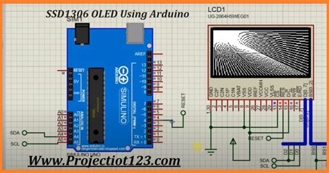
Pinout and Connections
To use the SSD1306 with your microcontroller or development board, you’ll need to connect the appropriate pins. The following table shows the typical pinout for the SSD1306:
| Pin | Name | Description |
|---|---|---|
| 1 | GND | Ground |
| 2 | VCC | Power supply (3.3V or 5V, depending on the module) |
| 3 | SCL/SCK | I2C clock line or SPI clock |
| 4 | SDA/MOSI | I2C data line or SPI MOSI (Master Out Slave In) |
| 5 | RST | Reset pin (active low) |
| 6 | DC | Data/Command selection (I2C mode: connected to GND, SPI mode: controlled by the microcontroller) |
| 7 | CS | Chip select (SPI mode only, active low) |
Note that the exact pinout may vary depending on the specific SSD1306 module or breakout board you are using. Always refer to the manufacturer’s documentation or pinout diagram for accurate connections.

Communicating with the SSD1306
To communicate with the SSD1306, you’ll need to use either the I2C or SPI protocol, depending on your chosen connection method.
I2C Communication
I2C is a simple and widely used two-wire communication protocol. To use I2C with the SSD1306, follow these steps:
- Connect the SDA and SCL pins of the SSD1306 to the corresponding pins on your microcontroller or development board.
- Connect the GND and VCC pins to the appropriate power supply (consult the module’s specifications for the correct voltage).
- If your module has a reset pin, connect it to the microcontroller’s reset pin or to VCC for automatic power-on reset.
- Connect the DC pin to GND to set the SSD1306 in I2C mode.
- In your code, initialize the I2C library and set the appropriate I2C address for the SSD1306 (usually 0x3C or 0x3D).
- Use the I2C library’s functions to send commands and data to the SSD1306.
SPI Communication
SPI offers faster data transfer speeds compared to I2C but requires more wires. To use SPI with the SSD1306, follow these steps:
- Connect the MOSI, SCK, CS, and DC pins of the SSD1306 to the corresponding pins on your microcontroller or development board.
- Connect the GND and VCC pins to the appropriate power supply (consult the module’s specifications for the correct voltage).
- If your module has a reset pin, connect it to the microcontroller’s reset pin or to VCC for automatic power-on reset.
- In your code, initialize the SPI library and set the appropriate SPI settings (clock speed, mode, and bit order).
- Use the SPI library’s functions to send commands and data to the SSD1306, toggling the CS and DC pins as needed to differentiate between command and data bytes.

Programming the SSD1306
To program the SSD1306, you can use various libraries and frameworks available for different programming languages and platforms. Some popular options include:
- Arduino: Adafruit_SSD1306, U8g2
- Python: Adafruit_SSD1306, Luma.OLED
- C/C++: U8g2, ssd1306 (for Raspberry Pi and other Linux-based systems)
These libraries provide high-level functions for initializing the display, setting pixels, drawing shapes, and displaying text. They often come with examples and documentation to help you get started quickly.
Here’s a simple example using the Adafruit_SSD1306 library for Arduino:
#include <Wire.h>
#include <Adafruit_GFX.h>
#include <Adafruit_SSD1306.h>

#define SCREEN_WIDTH 128
#define SCREEN_HEIGHT 64

Adafruit_SSD1306 display(SCREEN_WIDTH, SCREEN_HEIGHT, &Wire, -1);

void setup() {
  display.begin(SSD1306_SWITCHCAPVCC, 0x3C);
  display.clearDisplay();

  display.setTextSize(1);
  display.setTextColor(WHITE);
  display.setCursor(0, 0);
  display.println("Hello, world!");

  display.display();
}

void loop() {
  // Add your desired functionality here
}
This example initializes the display, clears it, and then displays the text “Hello, world!” in the top-left corner of the screen.

Displaying Graphics and Images
In addition to text, you can also display graphics and images on the SSD1306. Most libraries provide functions for drawing basic shapes like lines, rectangles, circles, and triangles. For more complex graphics and images, you can use bitmap data.
To display a bitmap image on the SSD1306, you’ll need to convert your image into a format compatible with the display. This usually involves converting the image to a monochrome (black and white) format and then generating an array of bytes representing the pixel data.
Many libraries offer tools or scripts to convert images into the required format. For example, the Adafruit_SSD1306 library for Arduino provides a bitmap converter tool that generates a header file with the bitmap data, which you can then include in your sketch.
Here’s an example of how to display a bitmap image using the Adafruit_SSD1306 library:
#include <Wire.h>
#include <Adafruit_GFX.h>
#include <Adafruit_SSD1306.h>
#include "bitmap.h"

#define SCREEN_WIDTH 128
#define SCREEN_HEIGHT 64

Adafruit_SSD1306 display(SCREEN_WIDTH, SCREEN_HEIGHT, &Wire, -1);

void setup() {
  display.begin(SSD1306_SWITCHCAPVCC, 0x3C);
  display.clearDisplay();

  display.drawBitmap(0, 0, bitmap_data, bitmap_width, bitmap_height, WHITE);
  display.display();
}

void loop() {
  // Add your desired functionality here
}
In this example, bitmap.h is the header file containing the bitmap data, and bitmap_width and bitmap_height are the dimensions of the bitmap image.
Power Management and Sleep Modes
The SSD1306 supports various power management and sleep modes to help reduce power consumption when the display is not in use. The chip offers three main power modes:
-
Normal mode: The default operating mode, where the display is fully powered and all functions are available.
-
Idle mode: A low-power mode where the display RAM remains unchanged, but the SSD1306 stops generating frame signals. The display can be quickly reactivated from this mode.
-
Sleep mode: The lowest power mode, where the display is turned off and the SSD1306 stops generating frame signals. Reactivating the display from sleep mode requires a full reinitialization.
To enter idle or sleep mode, you can send the appropriate command bytes to the SSD1306 using the I2C or SPI interface. Consult the SSD1306 datasheet and your library’s documentation for the specific commands and functions to use.
Here’s an example of how to enter and exit sleep mode using the Adafruit_SSD1306 library:
// Enter sleep mode
display.ssd1306_command(SSD1306_DISPLAYOFF);

// Delay or perform other tasks while in sleep mode
delay(1000);

// Exit sleep mode
display.ssd1306_command(SSD1306_DISPLAYON);
Troubleshooting and Common Issues
When working with the SSD1306, you may encounter some common issues. Here are a few troubleshooting tips:
-
Display not initializing: Double-check your wiring connections, ensure that the correct communication interface (I2C or SPI) is being used, and verify that the power supply voltage is within the specified range.
-
Incorrect display contrast: If the display appears too dim or too bright, adjust the contrast using the dedicated contrast pin or the appropriate library function.
-
Garbled or missing display output: Ensure that you are sending the correct command and data bytes to the SSD1306. Verify that your bitmap data is formatted correctly and that the dimensions match the display size.
-
I2C or SPI communication issues: Check that the I2C or SPI libraries are properly initialized and that the correct pins are being used. Verify that the clock speed and other settings match the SSD1306’s requirements.
If you continue to experience issues, consult the documentation for your specific SSD1306 module, library, and microcontroller or development board. Many online resources, forums, and communities can also provide helpful advice and solutions.
Frequently Asked Questions (FAQ)
-
What is the difference between the SSD1306 and other OLED display controllers?
The SSD1306 is a widely used and well-supported OLED display controller, specifically designed for small-sized displays with a resolution of 128×64 pixels. Other OLED display controllers, such as the SH1106 or the SSD1351, may offer different resolutions, color depths, or features, but the SSD1306 remains a popular choice for its simplicity and extensive library support. -
Can I use the SSD1306 with a different display resolution?
While the SSD1306 is primarily designed for 128×64 pixel displays, it can be used with other resolutions, such as 128×32 or 96×16 pixels. However, you may need to modify your code and graphics to accommodate the different resolution, and not all libraries may support alternative resolutions out of the box. -
How do I adjust the display contrast?
The SSD1306 has a dedicated contrast pin that allows you to adjust the display contrast using a potentiometer or a PWM signal from your microcontroller. Some libraries also provide functions to set the contrast programmatically. Consult your library’s documentation for specific instructions on adjusting the contrast. -
Can I display color images on the SSD1306?
No, the SSD1306 is a monochrome display controller, meaning it can only display black and white (or grayscale) images. If you require a color display, you’ll need to use a different OLED display controller, such as the SSD1351 or the ST7735. -
What is the maximum refresh rate of the SSD1306?
The SSD1306’s maximum refresh rate depends on several factors, including the communication interface (I2C or SPI), the clock speed, and the amount of data being transferred. In general, the SSD1306 can achieve refresh rates of up to 60 Hz, which is sufficient for most applications. However, the actual refresh rate may be lower depending on your specific setup and the complexity of the displayed content.
Conclusion
The SSD1306 is a versatile and widely used OLED display controller that enables the creation of small, low-power, and high-contrast displays for various applications. With its support for both I2C and SPI communication interfaces, flexible mapping options, and extensive library support, the SSD1306 is an excellent choice for projects requiring simple graphical displays.
By understanding the SSD1306’s features, pinout, and communication protocols, you can easily integrate this display controller into your projects. Whether you’re using Arduino, Python, or C/C++, there are numerous libraries and resources available to help you get started with the SSD1306 quickly.
Remember to consider factors such as power management, bitmap image formatting, and troubleshooting common issues when working with the SSD1306. By following best practices and consulting relevant documentation and resources, you can create engaging and informative displays for your projects using the SSD1306 OLED display controller.


Leave a Reply