Introduction
A printed circuit board (PCB) mechanically supports and electrically connects electronic components using conductive tracks, pads and other features etched from copper sheets laminated onto a non-conductive substrate. PCBs can be rigid, flexible or semi-flexible. Semi-flexible PCBs provide a compromise between the rigidity of rigid PCBs and the flexibility of flex PCBs. They are becoming more popular as electronics become more compact and require more flexible form factors.
What are Semi-Flexible PCBs?
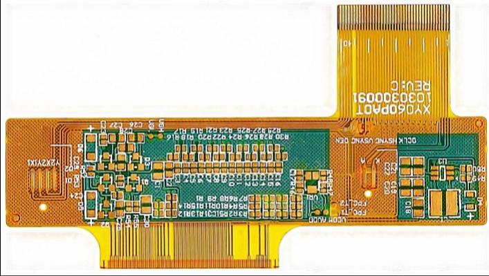
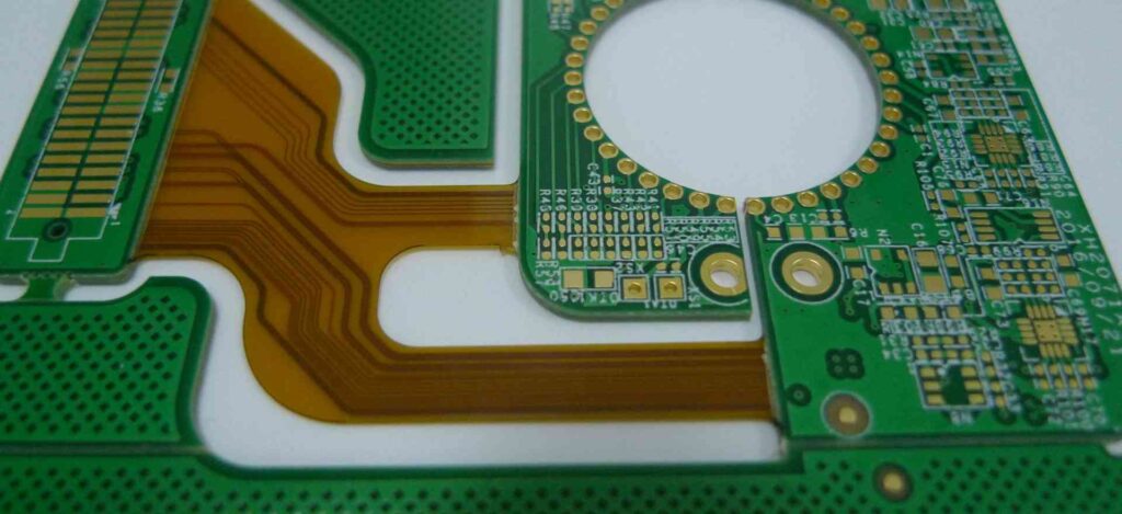
Semi-flexible PCBs, also called rigid-flex PCBs, use flexible PCB materials for portions of the board while retaining rigid sections for components requiring mechanical stability. This allows the board to conform to space constraints while still providing a solid mounting surface.
Rigid sections are typically made of higher layer count FR-4 or polyimide laminates. Flexible sections use 1 to 4 layer polyimide films bonded with acrylic, epoxy or polyimide adhesives. Semi-flexible boards can have multiple rigid and flex sections in complex configurations.
Key Characteristics:
- Combines rigid and flexible materials
- Bends predictably along defined flex areas
- Retains rigidity in component mounting sections
- Can have complex geometries with unlimited layers
- Lightweight and thin
- Durable construction
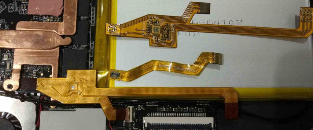
Semi-flex PCBs provide integrated interconnects between multiple PCB assemblies in products where space is limited. They can wrap around edges and fold into compact mechanisms. The rigid sections provide stability for surface mount components.
Benefits of Using Semi-Flex PCBs
Space savings
- Tightly conforms to product enclosures
- Folds into complex shapes
- Eliminates external cabling
Reliability
- Integrated interconnects avoid connectors
- One-piece design eliminates separations
- Consistent impedance control
Design freedom
- Unlimited configurations
- Mix rigid and flex as needed
- Embed components in flex areas
- Miniaturization potential
Performance
- Careful impedance control
- Low capacitance flexible sections
- Reduced noise and crosstalk
- High-speed signaling support
Design Considerations
Semi-flex PCB design requires special considerations for the integration of rigid and flex materials.
Layer Stacking
The rigid sections typically use normal symmetrical layer stacks with a central dielectric core, while the flex sections have unbalanced layer counts. Special care must be taken in layer transitions.
Bending Radius
The flexible sections must be designed to avoid exceeding minimum bend radii, typically defined by the flex laminate manufacturer. Inside bend radii are usually around 3-10x the laminate thickness.
Component Placement
Heavier components should be placed in rigid sections while lighter components can be mounted in flex areas. Components in flex areas require special adhesive to prevent cracking.
Routing
Traces between rigid and flex sections should be carefully transitioned to avoid tearing during bending. Teardrop pads help relieve stress concentrations.
Manufacturing Process
Semi-flex PCB fabrication involves specialized processes and materials.
Laminate Materials
The laminate materials must be compatible for bonding. Common material combinations include polyimide films bonded with acrylic, epoxy or polyimide adhesives.
Layer Alignment
The conductive layers must be precisely aligned between the multiple materials to ensure reliable interconnection.
Etching and Plating
Photolithographic patterning and copper plating processes tailored for dissimilar material properties.
Via Formation
Holes are drilled or laser ablated then plated to form vertical interconnects between layers.
Patterning
Complex panels with 100s of PCBs are fabricated for economy of scale then singulated.
Assembly
Stiffeners, brackets or spacers may be added for structural stability.
Applications
Semi-flex PCBs support many applications not well served by rigid or flex boards alone.
Consumer Electronics
- Phones
- Laptops
- Wearables
- Digital cameras
Automotive
- Instrument panels
- Infotainment systems
- Sensors
Medical
- Hearing aids
- Patient monitoring
- Implants
Industrial
- Robotics
- Avionics
- Oil exploration
Cost Considerations
Semi-flex PCBs have a higher cost than rigid PCBs, but they can reduce system cost in several ways:
- Eliminating connectors and cabling
- Reduced assembly cost
- Smaller and lighter final product
- Design innovation possibilities
For medium to high volume products with space constraints, the benefits usually outweigh the extra PCB cost.
FQA about Semi-Flex PCBs
Q: Why use semi-flex PCBs instead of rigid or flex PCBs?
A: Semi-flex PCBs provide the benefits of both rigid and flex PCBs in one design. The rigid sections allow mounting components while the flex sections provide dynamic movement and 3D configuration. They are ideal when a design needs both rigidity for stability and flexibility for compactness or motion.
Q: What types of adhesives are used in semi-flex PCBs?
A: The rigid and flex materials are bonded with adhesives tailored to the materials used. Typical adhesive choices include acrylic, epoxy and polyimide adhesives. The adhesive must withstand flexing without cracking or delaminating.
Q: What are some best practices for routing semi-flex PCBs?
A: Use teardrop pads at junctions between rigid and flex areas to reduce stress concentrations. Route wider traces on outer layers and use blind and buried vias when possible. Carefully manage differential pair lengths and impedance changes from rigid to flex sections.
Q: What limits the minimum bend radius on a semi-flex PCB?
A: The minimum bend radius is limited by the flex laminate material, copper thickness, and number of flexible layers. Typical minimum inside bend radii range from 3 to 10 times the laminate thickness. Exceeding this can crack copper or damage materials.
Q: How are components mounted in flexible areas on a semi-flex PCB?
A: Lightweight surface mount components can be attached directly using special flex adhesives. For heavier components, openings in the flex layers can hold mounted components in rigid sections. Flex sections can also incorporate cutouts to allow rigid component anchors.


Leave a Reply