Introduction to RJ45 Connectors and Pinouts
RJ45 connectors are widely used in computer networking applications, serving as the standard interface for Ethernet connections. These connectors, also known as 8P8C (8 Position 8 Contact), provide a reliable and efficient means of transmitting data over twisted pair cables. Understanding the pinout configuration of RJ45 connectors is crucial for network professionals, IT technicians, and anyone involved in setting up or troubleshooting network connections.
In this comprehensive guide, we will delve into the world of RJ45 connector pinouts, exploring their significance, different wiring standards, and practical applications. Whether you are a beginner seeking to grasp the basics or an experienced professional looking to enhance your knowledge, this article will provide you with valuable insights and information.
What are RJ45 Connectors?
RJ45 connectors are compact, rectangular plugs and jacks used to terminate and connect Ethernet cables. They feature eight pins, each of which plays a specific role in transmitting data signals. The term “RJ45” stands for “Registered Jack 45,” referring to the standardized interface specified by the Federal Communications Commission (FCC) in the United States.
Key Features of RJ45 Connectors
- 8 Pins: RJ45 connectors have eight pins, allowing for the transmission of four pairs of data signals.
- Compact Size: The small form factor of RJ45 connectors makes them ideal for high-density networking environments.
- Locking Mechanism: RJ45 connectors feature a locking tab that securely holds the plug in place, preventing accidental disconnections.
- Compatibility: RJ45 connectors are compatible with a wide range of Ethernet standards, including 10BASE-T, 100BASE-TX, and 1000BASE-T.

Understanding Rj45 Pinouts
The arrangement of the eight pins in an RJ45 connector is known as the pinout. Each pin is assigned a specific function, and the order in which the wires are connected to these pins determines the type of Ethernet cable and its intended use. Let’s take a closer look at the RJ45 pinout and its significance.
RJ45 Pinout Diagram
The following table illustrates the standard RJ45 pinout diagram:
| Pin | Wire Color (T568A) | Wire Color (T568B) |
|---|---|---|
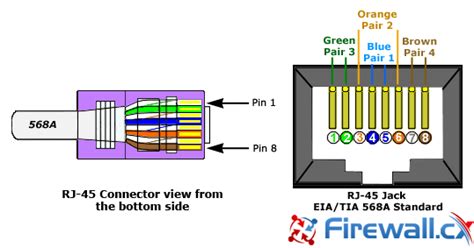
| 1 | Green/White | Orange/White |
| 2 | Green | Orange |
| 3 | Orange/White | Green/White |
| 4 | Blue | Blue |
| 5 | Blue/White | Blue/White |
| 6 | Orange | Green |
| 7 | Brown/White | Brown/White |
| 8 | Brown | Brown |
As shown in the table, there are two commonly used wiring standards for RJ45 connectors: T568A and T568B. The difference between these standards lies in the order of the colored wires connected to pins 1, 2, 3, and 6.
T568A vs. T568B
- T568A: In the T568A wiring standard, the green and orange pairs are swapped compared to T568B. This standard is less commonly used but is still recognized as a valid configuration.
- T568B: The T568B wiring standard is the more widely adopted configuration for Ethernet cables. It is the default standard for most off-the-shelf Ethernet patch cables.
While both T568A and T568B are acceptable wiring standards, it is essential to maintain consistency throughout a network to ensure proper connectivity and avoid any potential issues.

Types of Ethernet Cables and Their Pinouts
Ethernet cables come in different categories, each designed for specific networking requirements. Let’s explore the most common types of Ethernet cables and their corresponding pinouts.
Category 5 (Cat5) Cables
Category 5 cables, also known as Cat5, are legacy Ethernet cables that support data transmission speeds up to 100 Mbps. They consist of four twisted pairs of copper wires and can be terminated with RJ45 connectors using either the T568A or T568B wiring standard.
Category 5e (Cat5e) Cables
Category 5e cables, an enhanced version of Cat5, offer improved performance and support data transmission speeds up to 1 Gbps. They are backward compatible with Cat5 and follow the same pinout configuration.
Category 6 (Cat6) Cables
Category 6 cables provide higher bandwidth and support data transmission speeds up to 10 Gbps over shorter distances. They have a more stringent specification for crosstalk reduction and use thicker copper wires compared to Cat5 and Cat5e. Cat6 cables can be terminated with RJ45 connectors using either T568A or T568B wiring.
Category 6a (Cat6a) Cables
Category 6a cables are an augmented version of Cat6, offering even better performance and supporting data transmission speeds up to 10 Gbps over longer distances. They have additional shielding to minimize crosstalk and electromagnetic interference (EMI). Cat6a cables follow the same pinout configuration as Cat6.

Straight-Through vs. Crossover Cables
When it comes to connecting network devices, there are two main types of Ethernet cables: straight-through and crossover cables. Understanding the difference between these cable types and their pinouts is crucial for establishing proper network connectivity.
Straight-Through Cables
Straight-through cables, also known as patch cables, are the most commonly used Ethernet cables. They are used to connect dissimilar devices, such as a computer to a network switch or a router to a modem. In a straight-through cable, the pinout configuration is identical on both ends, following either the T568A or T568B wiring standard.
Crossover Cables
Crossover cables are used to connect similar devices directly, such as connecting two computers or two switches together without the need for a network switch. In a crossover cable, the transmit and receive pairs are swapped between the two ends of the cable. Specifically, pins 1 and 2 are crossed with pins 3 and 6.
| Pin | Wire Color (End 1) | Wire Color (End 2) |
|---|---|---|
| 1 | Green/White | Orange/White |
| 2 | Green | Orange |
| 3 | Orange/White | Green/White |
| 4 | Blue | Blue |
| 5 | Blue/White | Blue/White |
| 6 | Orange | Green |
| 7 | Brown/White | Brown/White |
| 8 | Brown | Brown |
With the advent of auto-sensing technology in modern network devices, the need for crossover cables has diminished. Many devices can now automatically detect and adjust to the cable type, allowing the use of straight-through cables in most scenarios.
Crimping and Terminating RJ45 Connectors
Properly crimping and terminating RJ45 connectors is essential for creating reliable Ethernet connections. Here are the steps involved in crimping and terminating RJ45 connectors:
- Strip the Cable: Use a cable stripper to remove about 1 inch of the outer jacket from the end of the Ethernet cable, exposing the twisted pairs of wires inside.
- Untwist and Arrange the Wires: Untwist each pair of wires and arrange them in the desired order according to the chosen wiring standard (T568A or T568B). Ensure that the wires are straight and aligned.
- Trim the Wires: Using wire cutters, trim the wires to a uniform length, leaving approximately 1/2 inch of exposed wire.
- Insert Wires into the RJ45 Connector: Carefully insert the arranged wires into the RJ45 connector, ensuring that each wire is fully seated into its corresponding pin slot. The wires should reach the end of the connector.
- Crimp the Connector: Place the RJ45 connector into the crimping tool, making sure it is properly positioned. Squeeze the handles of the crimping tool firmly to secure the connector onto the wires.
- Test the Connection: Use a cable tester to verify the integrity of the crimped connection and ensure that all pins are properly connected.
Following these steps and using high-quality crimping tools and RJ45 connectors will help ensure reliable and stable network connections.
Troubleshooting RJ45 Connector Issues
Despite proper crimping and termination, issues can sometimes arise with RJ45 connectors. Here are some common problems and troubleshooting tips:
Loose or Damaged Connectors
- Check for any visible damage to the RJ45 connector, such as bent pins or a cracked housing.
- Ensure that the connector is securely inserted into the jack and that the locking tab is engaged.
- If the connector is damaged, re-crimp the cable with a new RJ45 connector.
Incorrect Wiring
- Verify that the wires are arranged correctly according to the chosen wiring standard (T568A or T568B).
- Check for any crossed or swapped wires, which can lead to connectivity issues.
- Use a cable tester to identify any wiring errors and pinpoint the specific pins affected.
Damaged Cable
- Inspect the Ethernet cable for any physical damage, such as cuts, kinks, or crushed sections.
- Test the cable using a cable tester to check for continuity and identify any broken or shorted wires.
- If the cable is damaged, replace it with a new one.
Incompatible Devices
- Ensure that the connected devices support the same Ethernet standard (e.g., 10BASE-T, 100BASE-TX, 1000BASE-T).
- Verify that the devices are configured correctly and that the network settings match.
- Check if a crossover cable is required for direct device-to-device connection, or use auto-sensing devices that can handle both straight-through and crossover cables.
By understanding these common issues and applying the appropriate troubleshooting techniques, you can effectively resolve RJ45 connector problems and maintain a stable network connection.
Best Practices for RJ45 Connector Installation
To ensure optimal performance and reliability of RJ45 connectors, consider the following best practices:
- Use High-Quality Components: Invest in high-quality RJ45 connectors and Ethernet cables from reputable manufacturers to minimize the risk of connectivity issues.
- Follow Proper Wiring Standards: Consistently follow the chosen wiring standard (T568A or T568B) throughout the network to avoid compatibility problems.
- Maintain Consistent Cable Length: Keep Ethernet cable lengths within the recommended limits for the specific category to ensure signal integrity and minimize attenuation.
- Use Appropriate Tools: Use dedicated crimping tools and cable strippers designed for RJ45 connectors to ensure precise and reliable termination.
- Label Cables and Ports: Clearly label Ethernet cables and network ports to facilitate easy identification and troubleshooting.
- Test Connections: Always test the crimped RJ45 connectors and Ethernet cables using a cable tester to verify proper connectivity and identify any issues.
- Avoid Excessive Bending: When routing Ethernet cables, avoid sharp bends or excessive strain on the connectors to prevent damage and maintain signal quality.
- Provide Strain Relief: Use cable ties or cable management solutions to provide strain relief and prevent excessive pulling or tugging on the RJ45 connectors.
By adhering to these best practices, you can minimize the occurrence of RJ45 connector issues and ensure a stable and reliable network infrastructure.
Frequently Asked Questions (FAQ)
- What is the difference between RJ45 and Ethernet?
-
RJ45 refers to the physical connector and jack used for Ethernet connections, while Ethernet is the networking technology that defines the communication protocols and standards for data transmission over twisted pair cables.
-
Can I mix T568A and T568B wiring standards in the same network?
-
While it is technically possible to mix T568A and T568B wiring standards, it is highly recommended to maintain consistency throughout the network to avoid potential connectivity issues and simplify troubleshooting.
-
How do I know if I need a crossover cable?
-
Crossover cables are typically used when connecting two similar devices directly, such as connecting two computers or two switches. However, with the prevalence of auto-sensing technology in modern network devices, the need for crossover cables has diminished, and straight-through cables can be used in most scenarios.
-
What is the maximum length of an Ethernet cable?
-
The maximum length of an Ethernet cable depends on the cable category and the Ethernet standard being used. For example, Cat5 and Cat5e cables have a maximum length of 100 meters (328 feet) for 10/100 Mbps Ethernet, while Cat6 cables have a maximum length of 55 meters (180 feet) for 10 Gbps Ethernet.
-
Can I crimp RJ45 connectors without a crimping tool?
- While it is theoretically possible to crimp RJ45 connectors without a dedicated crimping tool, it is not recommended. Crimping tools are designed to provide the necessary pressure and precision for a reliable and secure connection. Attempting to crimp RJ45 connectors without the proper tool can lead to poor connections and potential damage to the connector or cable.
Conclusion
Understanding RJ45 connector pinouts is essential for anyone involved in computer networking. By comprehending the different wiring standards, cable categories, and crimping techniques, you can effectively create and maintain reliable Ethernet connections. Whether you are setting up a new network or troubleshooting existing connections, having a solid grasp of RJ45 pinouts will empower you to tackle connectivity challenges with confidence.
Remember to follow best practices, use high-quality components, and consistently adhere to wiring standards to ensure optimal network performance. With the knowledge gained from this comprehensive guide, you are well-equipped to navigate the world of RJ45 connectors and excel in your networking endeavors.


Leave a Reply