Rigid flex PCBs, also known as flex-rigid PCBs, represent an exciting innovation in printed circuit board (PCB) design. These boards provide the ability to integrate the reliability and sturdiness of a rigid PCB with the dynamic flexibility of a flex PCB. In doing so, rigid flex PCBs open up new possibilities for product designers across a variety of high-tech industries.
What Exactly Are Rigid Flex PCBs?
Combining Rigid and Flexible Substrates
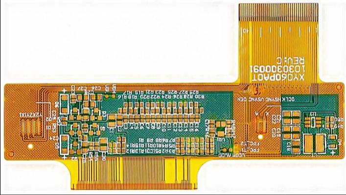
As the name implies, rigid flex PCBs consist of both rigid and flexible materials laminated together into a single circuit board. The rigid sections of the PCB provide structural stability similar to a traditional PCB fabricated from materials like FR-4. The flexible sections on the other hand allow for dynamic flexing and bending of the board.
Hinges Integrate Rigid Sections
The rigid and flexible substrates are integrated using flexural hinges designed into the PCB layout. These plated hinges provide constrained points of dynamic flexion between the rigid segments of the board. This allows the rigid sections to bend and fold in relation to one another, while maintaining structural stability and integrity of each segment.
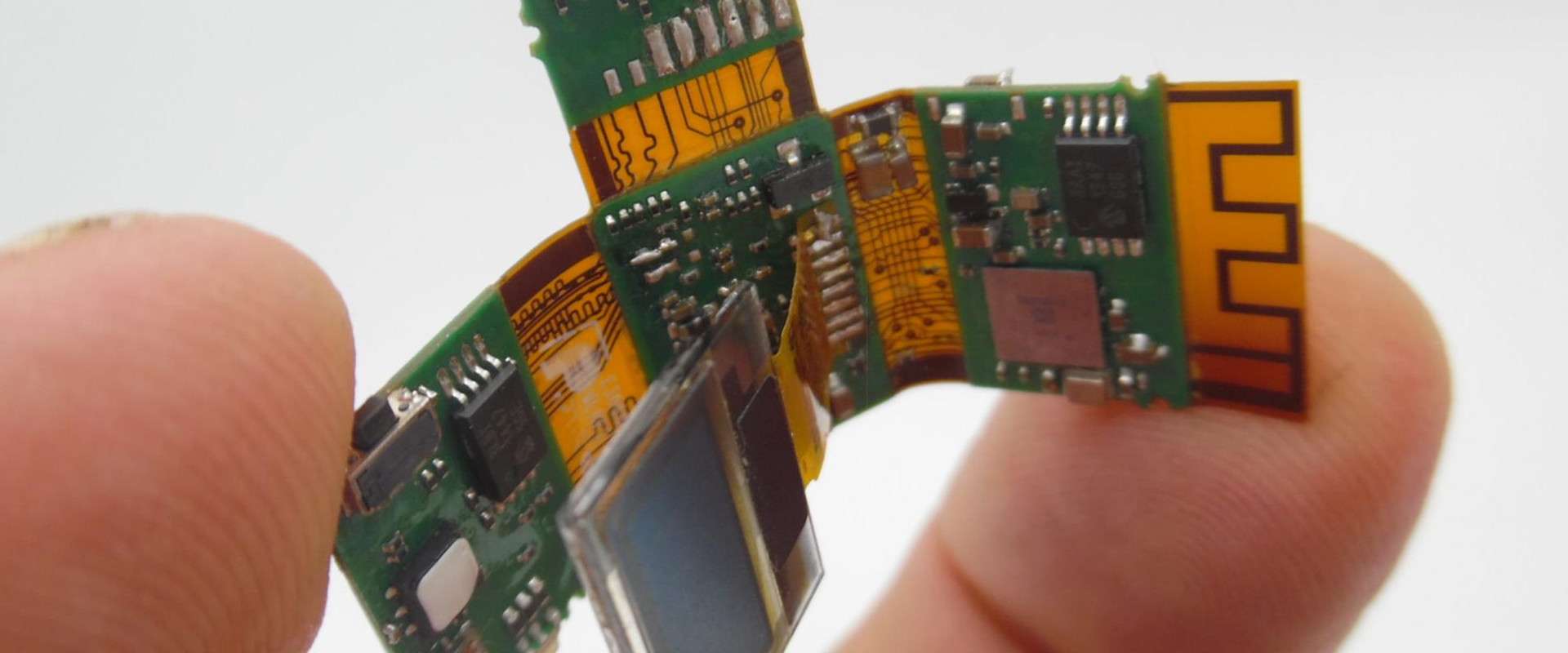
Enabling 3D Circuit Integration
By combining rigid stability and flexible articulation, rigid flex PCBs enable efficient 3D packaging and stacking of PCBAs. Multiple rigid segments containing components and circuitry can be integrated into a single assembly through flexible joints and interconnections. This allows for greater functionality in a smaller footprint, ideal for complex or space-constrained electronic devices.
Key Benefits of Rigid Flex PCBs
There are several key benefits that make rigid flex PCBs an attractive choice for many electronics applications:
Adaptability
- The flexible hinges and joints enable conformability to different shapes, surfaces, and spaces. Rigid flex PCBs can adapt to fit where rigid boards cannot.
Dynamic Flexion
- The flex joints maintain reliability with dynamic bending and folding motions, preventing failures due to flexing stresses.
Efficient 3D Packaging
- By folding and stacking rigid segments, rigid flex PCBs allow more compact 3D arrangements than rigid boards.
Enhanced Reliability
- Rigid sections provide structural stability while flex areas absorb stresses from motion and vibration. This relieves strain on solder joints.
Design Freedom
- Rigid flex PCBs free product designers from many traditional design constraints, opening new possibilities.
Light Weight
- By consolidating multiple PCBAs into one rigid flex assembly, overall weight can be reduced.
Rigid Flex PCB Applications
The unique benefits of rigid flex PCBs make them an ideal choice for products and devices where flexibility, reliability, and efficient packaging are key requirements. Here are some examples of where rigid flex PCBs are commonly used:
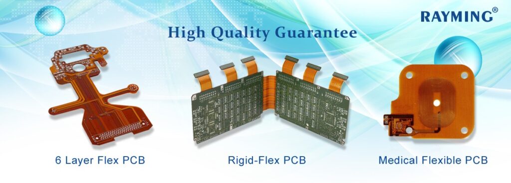
- Wearable electronics
- Medical devices
- Industrial IoT and robotics
- Aerospace and defense products
- Consumer electronics and gadgets
- Automotive electronics
For wearable technology like fitness trackers and smart watches, rigid flex PCBs allow for ergonomic designs that can conform to the human body. In medical devices like imaging systems and implants, they provide reliable connections that can endure repeated flexing motions. For electronics in automobiles and aircraft, the boards can absorb vibration and shock. Across many industries, the adaptability and resilience of rigid flex PCBs enable innovative and efficient product designs.
Rigid Flex PCB Design Considerations
Designing a rigid flex PCB requires special considerations beyond standard PCB layout and manufacturing. Here are some key factors to keep in mind:
Layer Stacking
Rigid layers typically use thicker, higher Tg materials than flex layers. Layer stacking and transitions must be designed appropriately to avoid issues like stress points or impedance mismatch.
Dynamic Bend Radius
The bend radius for flex areas impacts reliability with continual flexing. Avoid sharp folds and account for any dynamic changes in bend radius.
Termination at Flex-to-Rigid Joints
Use tear drops, rounded corners, or other smooth transitions where traces terminate at rigid-flex junctions to reduce potential for cracks.
Flexible and Rigid Component Placement
Strategic placement of components can distribute stresses, loads, and weight across both rigid and flex sections.
Flex Patterning Constraints
Rigid and flexible layers often require different patterning processes. Panelization must align rigid and flex fabrication steps.
Protective Coatings
Coverage of flex areas with protective lacquer or solder mask helps prevent abrasion and material degradation over repetitive bending.
With sound design principles and advanced manufacturing capabilities, these considerations can be effectively addressed to yield reliable, high-performance rigid flex PCB assemblies.
Rigid Flex PCB Material Selection
Several types of materials are commonly used in rigid flex PCB fabrication. The rigid substrate is typically a traditional glass-reinforced epoxy laminate like FR-4. The flexible substrate usually consists of a polyimide film such as DuPontTM Kapton® or UBE UPISEL-N. The table below compares properties of typical rigid and flex base materials for rigid-flex PCBs.
| Property | Rigid Substrate (FR-4) | Flex Substrate (Polyimide) |
|---|---|---|
| Glass Transition Temperature | 110-150°C | 250-350°C |
| Coefficient of Thermal Expansion | 12-20 ppm/°C | 15-25 ppm/°C |
| Dielectric Constant | 4.2-4.6 | 3.2-3.5 |
| Dielectric Strength | 400-600 V/mil | 5000-7000 V/mil |
| Young’s Modulus | ~20 GPa | ~2-5 GPa |
Polyimide films provide a robust flexible substrate with excellent thermal and mechanical properties to complement the rigid sections. FR-4, ceramic-filled PTFE composites, and other rigid laminates are options for the rigid layers as needed.
Manufacturing Processes for Rigid Flex PCBs
Specialized fabrication techniques and advanced PCB equipment are required to produce reliable rigid flex boards and assemblies. Here is an overview of key manufacturing processes:
Photolithography
High-precision photolithography techniques pattern the circuitry on individual flexible and rigid layers prior to lamination. Step and repeat processes are typically used.
Lamination
Layers of flex substrate, adhesive, and rigid laminates are stacked and laminated together under heat and pressure to form the base board. Precise alignment and layer transitions are critical.
Etching
Etching techniques like immersion or spray undercut form the conductive traces by selectively removing copper from laminated boards.
Hole Drilling
Laser drilling, mechanical drilling, and/or plasma etching are used to form vias and through holes for layer interconnections.
Plating and Coating
Electroless and electrolytic copper processes plate hole walls to form conductive interconnections between layers. Solder mask, coverlayers, and other coatings are also applied.
Testing and Inspection
Electrical testing combined with automated optical inspection at multiple stages ensures reliability and continuity of traces and interconnections.
The combination of specialized equipment and advanced fabrication expertise allows PCB manufacturers to volume produce complex, high-quality rigid flex circuits.
Rigid Flex PCB Assembly
To leverage the full benefits of rigid flex PCBs, assembly processes must also accommodate the hybrid rigid-flexible design. Some considerations include:
Layer Transitions
Components near layer transitions may require secondary operations like solder filleting to avoid stress points.
Flex Folding
Programmed unfolding/folding steps allow flexible sections to be properly oriented for placement and soldering.
Flex Component Mounting
Pick and place equipment must apply precise pressure to avoid damaging flex areas while placing components.
Inspection Accessibility
Full assembly inspection requires physical access to both sides of flexed joints. Fixtures may be needed to gain visual access.
By approaching rigid flex assembly with a focus on the unique material properties involved, surface mount and through-hole assembly can be adapted to handle combined rigid and flexible PCBs.
Rigid Flex PCB Cost Considerations
With the specialized materials, processes, and engineering expertise involved, rigid flex PCBs tend to have a higher cost than traditional rigid boards. However, they enable unique design possibilities that enhance functionality, reliability, and manufacturing efficiency. Some cost factors to keep in mind:
- Low volume projects often have higher unit costs, while higher volumes can achieve improved economy of scale.
- Design complexity with more layers or flex-rigid transitions adds cost. Simpler designs can reduce cost.
- Advanced assembly techniques drive cost up but may be required to handle complex rigid flex designs.
- Material costs for high-performance flexible substrates exceed standard PCB materials.
- Testing throughout fabrication is essential for quality but adds cost.
For many applications, the benefits of rigid flex PCBs outweigh the higher costs. As with any technology, costs can be managed through smart, efficient design. Innovative engineering combined with strategic manufacturing and sourcing partnerships can help manage rigid flex PCB costs effectively.
Frequently Asked Questions
What are the main advantages of rigid flex PCBs?
Rigid flex PCBs offer several key advantages including dynamic flexibilility, efficient 3D packaging, enhanced reliability under motion and vibration, design freedom from constraints of rigid boards, and lightweight consolidation of circuitry.
What products commonly use rigid flex PCBs?
Applications that benefit from flexibility and reliability under motion tend to use rigid flex PCBs. Examples include wearables, medical devices, robotics, automotive electronics, aerospace avionics, and consumer gadgets.
How do costs compare between rigid flex PCBs and rigid PCBs?
Rigid flex PCBs currently have a higher cost structure than traditional rigid boards. Advanced materials, complex fabrication, and specialized assembly all contribute to this pricing difference. However costs can be managed through efficient, innovative design.
What are key considerations when laying out a rigid flex PCB?
Careful design is needed around layer transitions, bend radiuses, termination points, component placement across rigid and flex areas, patterning constraints, and adding protective cover coatings. These areas require specialized engineering expertise.
How are components assembled on rigid flex PCBs?
Both surface mount and through hole components can be assembled on rigid flex PCBs. The combination of rigid and flexible materials in one assembly requires adaptations to conventional pick and place and soldering processes however.


Leave a Reply