Introduction to Raspberry Pi and ADC
The Raspberry Pi is a popular single-board computer that has revolutionized the world of DIY electronics and computing. Its versatility, affordability, and ease of use have made it a go-to choice for hobbyists, educators, and professionals alike. One of the many features that make the Raspberry Pi stand out is its ability to interface with various sensors and devices, including Analog-to-Digital Converters (ADCs).
In this comprehensive guide, we will explore the concept of ADCs and how they can be used with the Raspberry Pi to enhance your projects. We will cover the basics of ADCs, the different types available, and how to set up and use them with your Raspberry Pi.
What is an ADC?
An Analog-to-Digital Converter (ADC) is a device that converts analog signals into digital signals. Analog signals are continuous and can take on any value within a given range, while digital signals are discrete and can only take on specific values. ADCs are essential in many applications, such as data acquisition, signal processing, and control systems.
Why Use an ADC with Raspberry Pi?
The Raspberry Pi, like most digital devices, can only read and process digital signals. However, many sensors and devices output analog signals. To interface these devices with the Raspberry Pi, an ADC is required to convert the analog signals into digital signals that the Raspberry Pi can understand and process.
Types of ADCs for Raspberry Pi
There are several types of ADCs available for use with the Raspberry Pi. Each type has its own advantages and disadvantages, and the choice of ADC will depend on your specific application and requirements.
1. Built-in ADC (MCP3008)
The Raspberry Pi does not have a built-in ADC, but it does have an SPI interface that can be used to connect an external ADC. The MCP3008 is a popular choice for this purpose. It is a 10-bit ADC with 8 input channels, making it suitable for a wide range of applications.
Advantages:
– Easy to set up and use with the Raspberry Pi
– Relatively inexpensive
– Provides 8 input channels
Disadvantages:
– Limited resolution (10-bit)
– Slower sampling rate compared to other ADCs
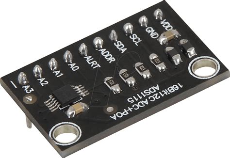
2. ADS1115
The ADS1115 is a 16-bit ADC with 4 input channels. It offers higher resolution and faster sampling rates compared to the MCP3008, making it suitable for more demanding applications.
Advantages:
– Higher resolution (16-bit)
– Faster sampling rates
– Programmable gain amplifier (PGA) for improved signal conditioning
Disadvantages:
– More expensive than the MCP3008
– Fewer input channels (4 vs. 8)
3. ADS1256
The ADS1256 is a high-precision, 24-bit ADC with 8 input channels. It is designed for applications that require extremely accurate measurements, such as scientific instrumentation and medical devices.
Advantages:
– Extremely high resolution (24-bit)
– 8 input channels
– Built-in programmable gain amplifier (PGA)
– Simultaneous sampling of multiple channels
Disadvantages:
– Significantly more expensive than other ADCs
– More complex to set up and use
| ADC | Resolution | Input Channels | Sampling Rate | Cost |
|---|---|---|---|---|
| MCP3008 | 10-bit | 8 | Moderate | Low |
| ADS1115 | 16-bit | 4 | Fast | Medium |
| ADS1256 | 24-bit | 8 | Fast | High |

Setting Up an ADC with Raspberry Pi
Now that we have explored the different types of ADCs available for the Raspberry Pi, let’s dive into the process of setting up an ADC with your Raspberry Pi.
Hardware Requirements
To set up an ADC with your Raspberry Pi, you will need the following hardware components:
- Raspberry Pi board (any model)
- ADC module (e.g., MCP3008, ADS1115, or ADS1256)
- Breadboard
- Jumper wires
- Analog sensor or device (e.g., temperature sensor, light sensor, or potentiometer)
Wiring the ADC to the Raspberry Pi
The wiring configuration will depend on the specific ADC module you are using. In this example, we will use the MCP3008 ADC.
- Connect the VDD pin of the MCP3008 to the 3.3V pin on the Raspberry Pi.
- Connect the VREF pin of the MCP3008 to the 3.3V pin on the Raspberry Pi.
- Connect the AGND pin of the MCP3008 to a GND pin on the Raspberry Pi.
- Connect the DGND pin of the MCP3008 to a GND pin on the Raspberry Pi.
- Connect the CLK pin of the MCP3008 to the SCLK pin (GPIO11) on the Raspberry Pi.
- Connect the DOUT pin of the MCP3008 to the MISO pin (GPIO9) on the Raspberry Pi.
- Connect the DIN pin of the MCP3008 to the MOSI pin (GPIO10) on the Raspberry Pi.
- Connect the CS pin of the MCP3008 to the CE0 pin (GPIO8) on the Raspberry Pi.
| MCP3008 Pin | Raspberry Pi Pin |
|---|---|
| VDD | 3.3V |
| VREF | 3.3V |
| AGND | GND |
| DGND | GND |
| CLK | SCLK (GPIO11) |
| DOUT | MISO (GPIO9) |
| DIN | MOSI (GPIO10) |
| CS | CE0 (GPIO8) |
Software Setup
To use the ADC with your Raspberry Pi, you will need to install the necessary software libraries and configure your Raspberry Pi to communicate with the ADC.
-
Update your Raspberry Pi:
sudo apt update

sudo apt upgrade -
Install the SPI library:
sudo apt install python-spidev -
Enable SPI interface:
sudo raspi-config
Navigate to “Interfacing Options” and enable SPI. -
Install the Adafruit_MCP3008 library:
sudo pip3 install Adafruit_MCP3008

Reading Analog Values with Python
Now that you have set up the hardware and software, you can start reading analog values from your sensor or device using Python.
Example Code
Here’s a simple Python script that demonstrates how to read analog values from a sensor connected to the MCP3008 ADC:
import time
import Adafruit_GPIO.SPI as SPI
import Adafruit_MCP3008

# Hardware SPI configuration:
SPI_PORT   = 0
SPI_DEVICE = 0
mcp = Adafruit_MCP3008.MCP3008(spi=SPI.SpiDev(SPI_PORT, SPI_DEVICE))

while True:
    # Read the analog value from channel 0
    analog_value = mcp.read_adc(0)
    voltage = analog_value * 3.3 / 1024
    print("Analog Value: %d, Voltage: %.2fV" % (analog_value, voltage))
    time.sleep(0.5)
This script does the following:
- Imports the necessary libraries (time, SPI, and Adafruit_MCP3008).
- Configures the hardware SPI settings.
- Initializes the MCP3008 ADC.
- Enters an infinite loop that:
- Reads the analog value from channel 0 of the ADC.
- Converts the analog value to voltage using the formula: voltage = (analog_value * 3.3) / 1024.
- Prints the analog value and voltage.
- Waits for 0.5 seconds before repeating the loop.

Applications of ADCs with Raspberry Pi
ADCs can be used in a wide range of applications with the Raspberry Pi. Here are a few examples:
1. Environmental Monitoring
You can use ADCs with various sensors to monitor environmental conditions, such as temperature, humidity, air quality, and light intensity. This data can be used to create automated systems that respond to changes in the environment, such as controlling a fan or adjusting lighting based on the ambient light level.
2. Industrial Process Control
In industrial settings, ADCs can be used to monitor and control various processes. For example, you can use an ADC with a pressure sensor to monitor the pressure in a pipeline and control a valve to maintain the desired pressure level.
3. Health Monitoring
ADCs can be used with various biosensors to monitor vital signs, such as heart rate, blood pressure, and glucose levels. This data can be used to create personalized health monitoring systems or to alert healthcare professionals in case of emergencies.
4. Audio and Video Processing
ADCs are essential components in audio and video processing applications. You can use an ADC with a microphone to record and process audio signals, or with a camera to capture and process video frames.
Conclusion
In this comprehensive guide, we have explored the concept of ADCs and how they can be used with the Raspberry Pi to enhance your projects. We have covered the basics of ADCs, the different types available, and how to set up and use them with your Raspberry Pi.
By mastering the use of ADCs with your Raspberry Pi, you can create a wide range of applications that interact with the analog world, from environmental monitoring and industrial process control to health monitoring and audio/video processing.
Frequently Asked Questions (FAQ)
-
Q: Can I use any analog sensor with an ADC and Raspberry Pi?
A: Most analog sensors can be used with an ADC and Raspberry Pi, as long as the sensor’s output voltage range is compatible with the ADC’s input range. Be sure to check the specifications of both the sensor and the ADC before connecting them. -
Q: How do I choose the right ADC for my project?
A: The choice of ADC depends on your project’s requirements, such as the required resolution, sampling rate, number of input channels, and budget. Consider the specific needs of your application and refer to the comparison table provided in this guide to select the most suitable ADC. -
Q: Can I use multiple ADCs with a single Raspberry Pi?
A: Yes, you can use multiple ADCs with a single Raspberry Pi. However, you will need to ensure that each ADC has a unique set of SPI pins and that your Raspberry Pi has enough available GPIO pins to accommodate all the ADCs. -
Q: How do I calibrate my ADC for accurate measurements?
A: ADC calibration involves measuring known reference voltages and adjusting the ADC’s output to match these voltages. The specific calibration process will depend on the ADC and the library you are using. Refer to the documentation of your chosen ADC and library for detailed calibration instructions. -
Q: Can I use an ADC with a Raspberry Pi to measure AC signals?
A: ADCs are designed to measure DC signals. To measure AC signals, you will need to first convert them to DC signals using a rectifier and a low-pass filter. Alternatively, you can use specialized AC voltage sensors that output a proportional DC signal, which can then be measured using an ADC.


Leave a Reply