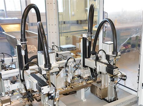
What is Pick-and-Place?
Pick-and-place refers to the process of automatically placing electronic components onto a PCB during the assembly process. This is done using specialized machines that can quickly and accurately place components based on the information provided in specific file formats.
The Role of Pick-and-Place Machines
Pick-and-place machines are essential in modern electronics manufacturing for several reasons:
- Speed: These machines can place components at a much faster rate than manual placement, significantly reducing assembly time.
- Accuracy: Pick-and-place machines can place components with high precision, ensuring proper alignment and reducing the risk of errors.
- Consistency: Automated placement ensures consistent quality across multiple PCBs, reducing the variability that can occur with manual placement.
Common Pick-and-Place File Formats
There are several file formats used in the pick-and-place process, each with its own characteristics and advantages. Let’s explore some of the most common formats:
1. Centroid File Format
The Centroid file format, also known as the .mnt file, is a widely used format in the industry. It contains information about the components, their placement coordinates, and rotation angles. The file is typically generated by CAD software during the PCB design process.
Centroid File Structure
A Centroid file consists of several sections:
- Header: Contains general information about the PCB, such as the board name, date, and units used.
- Component List: Lists all the components to be placed, including their reference designators, package types, and pickup points.
- Placement Data: Provides the X and Y coordinates and rotation angles for each component.
- Trailer: Marks the end of the file and may include additional comments or information.
Here’s an example of a simplified Centroid file:
H,TH,FPT-ABC123,RevA,2021-05-01
P,C1,0805,5.6,7.2,0
P,R1,0603,10.5,15.3,90
P,U1,SOIC-8,25.4,30.1,180
In this example, the header (H) specifies the board name, revision, and date. The component list (P) includes the reference designator, package type, X and Y coordinates, and rotation angle for each component.
2. Gerber X2 Format
The Gerber X2 format, an extension of the traditional Gerber format, includes additional metadata that facilitates the pick-and-place process. This format embeds component information directly into the Gerber files, eliminating the need for separate pick-and-place files.
Advantages of Gerber X2
- Streamlined Process: By integrating component information into the Gerber files, the Gerber X2 format simplifies the data exchange between design and manufacturing.
- Reduced Errors: Embedding component data directly into the Gerber files reduces the risk of discrepancies and errors that can occur when using separate pick-and-place files.
- Enhanced Traceability: Gerber X2 includes unique identifiers for each component, enabling better traceability throughout the manufacturing process.
3. ODB++ Format
The ODB++ (Open Database++) format is a comprehensive and intelligent format that includes not only pick-and-place information but also a complete set of PCB design data. It is a directory structure that contains multiple files, including the component placement data.
ODB++ Advantages
- Comprehensive Data: ODB++ includes all the necessary data for PCB fabrication and assembly, reducing the need for multiple file formats.
- Intelligent Format: The format includes features like netlists, component attributes, and design rules, enabling better communication between design and manufacturing.
- Versioning and Traceability: ODB++ supports versioning and includes unique identifiers for components, enhancing traceability and data management.
4. IPC-D-356 Format
The IPC-D-356 format, also known as the NetList format, is a text-based format that provides information about the components and their connections on the PCB. While primarily used for netlist information, it can also include component placement data.
IPC-D-356 File Structure
An IPC-D-356 file consists of several sections:
- Header: Contains general information about the PCB, such as the board name, date, and file version.
- Component List: Lists all the components on the PCB, including their reference designators and pin information.
- Net List: Specifies the connections between components and their respective pins.
- Footer: Marks the end of the file and may include additional comments or information.
Here’s an example of a simplified IPC-D-356 file:
%HEADER
BOARD_NAME,PCB-123
GENERATED_DATE,2021-05-01
%COMP
C1,2,1,2
R1,2,1,2
U1,8,1,2,3,4,5,6,7,8
%NETS
N000001,C1,1,R1,1
N000002,C1,2,U1,1
N000003,R1,2,U1,2
%END
In this example, the header section provides the board name and generation date. The component list (%COMP) includes the reference designator and pin count for each component. The net list (%NETS) specifies the connections between the component pins.

Choosing the Right Pick-and-Place File Format
When selecting a pick-and-place file format, consider the following factors:
- Compatibility: Ensure that the chosen format is compatible with your pick-and-place machine and the software used in your manufacturing process.
- Data Requirements: Consider the level of detail and information required for your specific manufacturing needs. Some formats may provide more comprehensive data than others.
- Ease of Use: Evaluate the ease of generating and managing the selected file format within your design and manufacturing workflow.
- Industry Standards: Take into account any industry standards or requirements that may influence your choice of file format.

Best Practices for Creating Pick-and-Place Files
To ensure accurate and efficient component placement, follow these best practices when creating pick-and-place files:
- Verify Component Data: Double-check the component information, such as reference designators, package types, and pin assignments, to avoid placement errors.
- Use Consistent Units: Ensure that the units used in the pick-and-place file match the units used in the PCB design and manufacturing process.
- Include Fiducial Markers: Incorporate fiducial markers in your PCB design and pick-and-place files to provide reference points for accurate component placement.
- Validate File Integrity: Perform thorough checks to ensure the completeness and accuracy of the pick-and-place file before submitting it for manufacturing.
- Collaborate with Manufacturers: Work closely with your PCB Assembly partners to ensure compatibility and adherence to their specific requirements and guidelines.

Frequently Asked Questions
1. Can I use multiple pick-and-place file formats in the same project?
While it’s possible to use multiple file formats, it’s generally recommended to stick to a single format throughout the project to maintain consistency and minimize the risk of errors.
2. What happens if there are discrepancies between the pick-and-place file and the PCB design?
Discrepancies between the pick-and-place file and the PCB design can lead to component placement errors. It’s crucial to ensure that the pick-and-place file accurately reflects the latest PCB design before proceeding with manufacturing.
3. How do I generate a pick-and-place file from my CAD software?
Most CAD software packages used for PCB design have built-in tools or plugins to generate pick-and-place files. Consult your CAD software documentation or support resources for specific instructions on generating the desired file format.
4. Can I manually edit a pick-and-place file?
While it’s possible to manually edit a pick-and-place file using a text editor, it’s generally not recommended unless you have a thorough understanding of the file format and the implications of the changes. Incorrect modifications can lead to placement errors and manufacturing issues.
5. What should I do if I encounter issues with my pick-and-place file during manufacturing?
If you encounter issues with your pick-and-place file during manufacturing, collaborate with your PCB assembly partner to identify and resolve the problem. They may provide guidance on file format requirements, troubleshooting steps, or suggest modifications to ensure successful component placement.
Conclusion
Pick-and-place file formats play a vital role in the accurate and efficient assembly of electronic components onto PCBs. By understanding the various formats, their characteristics, and best practices for creating these files, you can streamline your PCB manufacturing process and ensure high-quality results.
When selecting a pick-and-place file format, consider factors such as compatibility, data requirements, ease of use, and industry standards. Collaborate closely with your PCB assembly partners to ensure seamless integration and adherence to their specific guidelines.
By following best practices and maintaining clear communication throughout the design and manufacturing process, you can leverage the power of pick-and-place file formats to achieve precise component placement and optimize your PCB assembly workflow.
Key Takeaways
- Pick-and-place file formats provide essential information for accurate component placement on PCBs.
- Common formats include Centroid, Gerber X2, ODB++, and IPC-D-356, each with its own characteristics and advantages.
- Choosing the right file format depends on factors such as compatibility, data requirements, ease of use, and industry standards.
- Best practices for creating pick-and-place files include verifying component data, using consistent units, including fiducial markers, validating file integrity, and collaborating with manufacturers.
- Close collaboration and clear communication between design and manufacturing teams are essential for successful PCB assembly using pick-and-place file formats.
By understanding and effectively utilizing pick-and-place file formats, you can optimize your PCB assembly process, reduce errors, and ensure the highest quality of your electronic products.


Leave a Reply