What is the Gerber format?
The Gerber format is a vector-based data format that describes the layout of a PCB. It consists of a set of files, each representing a specific layer or aspect of the PCB design. These files contain information about the copper traces, solder mask, silkscreen, drill holes, and other features necessary for manufacturing the PCB.
The Gerber format was initially developed by the Gerber Systems Corp. in the 1960s for their vector photoplotters. Over time, it has evolved to accommodate the growing complexity of PCB designs and has become the de facto standard for the PCB industry.
Advantages of Using the Gerber Format
There are several reasons why the Gerber format has become the preferred choice for PCB manufacturing:
-
Simplicity: The Gerber format is a simple, text-based format that is easy to generate and interpret. It consists of human-readable ASCII commands that describe the PCB layout, making it accessible to both designers and manufacturers.
-
Reliability: The Gerber format has been extensively tested and proven to be reliable for PCB manufacturing. It ensures accurate and consistent representation of the PCB design, reducing the chances of errors during fabrication.
-
Widespread adoption: The Gerber format is supported by virtually all PCB design software and is accepted by most PCB manufacturers worldwide. This widespread adoption makes it easy to collaborate with different stakeholders in the PCB design and manufacturing process.
-
Flexibility: The Gerber format supports a wide range of PCB features, including complex shapes, apertures, and drill holes. It can accurately describe both simple and intricate PCB designs.

Structure of Gerber Files
A complete set of Gerber files for a PCB design typically includes the following:
-
Copper layers: These files represent the conductive copper traces on the PCB. There is a separate file for each copper layer, such as the top layer, bottom layer, and inner layers (if applicable).
-
Solder mask layers: These files define the areas on the PCB that should be covered with solder mask, which is a protective coating that prevents short circuits and oxidation.
-
Silkscreen layers: These files contain the text, logos, and other markings that are printed on the PCB for identification and assembly purposes.
-
Drill files: These files specify the location, size, and type of drill holes on the PCB, including through holes and vias.
-
Profile layer: This file defines the outline and shape of the PCB, including any cutouts or irregular boundaries.
Each Gerber file consists of a sequence of commands that describe the geometry and properties of the PCB features. These commands include:
- Aperture definitions: Specify the shapes and sizes of the apertures (e.g., circles, rectangles, polygons) used to draw the PCB features.
- Draw commands: Instruct the plotter or photo-imaging equipment to expose or draw the specified apertures at specific locations on the PCB.
- Polarity commands: Define whether the drawn features should be additive (exposed) or subtractive (not exposed).
- Attribute commands: Provide additional information about the PCB features, such as the layer type, color, and thickness.

Generating Gerber Files
Most PCB design software tools have built-in functionality to generate Gerber files from the PCB design. The process typically involves the following steps:
-
Complete the PCB design in the software, ensuring that all layers and features are properly defined.
-
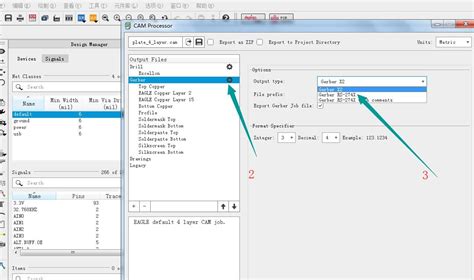
Configure the Gerber export settings, specifying the desired file format (e.g., RS-274X), file naming convention, and layer mapping.
-
Generate the Gerber files by executing the export command. The software will create a set of files, one for each layer or aspect of the PCB design.
-
Review the generated Gerber files using a Gerber viewer or CAM (Computer-Aided Manufacturing) software to ensure accuracy and completeness.
-
Package the Gerber files along with any necessary documentation (e.g., drill files, fabrication notes) and send them to the PCB manufacturer for fabrication.

Gerber File Extensions and Naming Conventions
Gerber files use specific file extensions to indicate the layer or aspect of the PCB they represent. Some common file extensions include:
.GTL: Top copper layer.GBL: Bottom copper layer.GTS: Top solder mask layer.GBS: Bottom solder mask layer.GTO: Top silkscreen layer.GBO: Bottom silkscreen layer.GKO: Board outline/profile layer.DRL: Drill file
In addition to file extensions, it is important to follow a consistent naming convention for Gerber files to avoid confusion and ensure smooth communication with the PCB manufacturer. The naming convention should clearly identify the PCB design, revision, and layer type.
Best Practices for Creating Gerber Files
To ensure the best results when working with Gerber files, consider the following best practices:
-
Use a consistent naming convention: Adopt a clear and consistent naming convention for your Gerber files to avoid confusion and improve communication with the PCB manufacturer.
-
Include all necessary layers: Ensure that you generate Gerber files for all the required layers of your PCB design, including copper, solder mask, silkscreen, and drill layers.
-
Verify file accuracy: Use a Gerber viewer or CAM software to review the generated Gerber files and ensure that they accurately represent your PCB design. Check for any missing features, incorrect apertures, or formatting issues.
-
Communicate with the PCB manufacturer: Provide clear instructions and any additional documentation to the PCB manufacturer to avoid misunderstandings and ensure a smooth fabrication process.
-
Keep a backup: Always keep a backup of your Gerber files and PCB design files for future reference and revision control.
Frequently Asked Questions (FAQ)
-
What is the difference between RS-274D and RS-274X Gerber formats?
RS-274D is the original Gerber format, while RS-274X is an extended version that includes additional features and commands. RS-274X is the more modern and widely used format in the PCB industry today. -
Can Gerber files be edited?
Gerber files are not intended to be edited directly. If changes are needed, it is recommended to modify the PCB design in the original design software and regenerate the Gerber files. -
Are Gerber files compatible with all PCB manufacturers?
Yes, almost all PCB manufacturers worldwide accept Gerber files. It is the most widely used and standardized format for PCB fabrication. -
What is a Gerber viewer, and why is it important?
A Gerber viewer is a software tool that allows you to view and analyze Gerber files. It is important to use a Gerber viewer to verify the accuracy and completeness of your Gerber files before sending them to the PCB manufacturer. -
Can Gerber files be used for other manufacturing processes besides PCBs?
While Gerber files are primarily used for PCB manufacturing, they can also be used for other applications that involve 2D vector-based data, such as sign making, engraving, and laser cutting.
Conclusion
The RS-274X (Extended Gerber) format is an essential tool for anyone involved in PCB design and manufacturing. It provides a standardized and reliable way to communicate PCB design information, ensuring accurate and efficient fabrication. By understanding the structure and best practices for creating Gerber files, designers can streamline the PCB manufacturing process and achieve high-quality results.
As the electronics industry continues to evolve, the Gerber format remains a vital link between PCB design and manufacturing. Its simplicity, reliability, and widespread adoption make it the go-to choice for PCB fabrication worldwide.
| File Extension | Layer/Aspect |
|---|---|
| .GTL | Top copper layer |
| .GBL | Bottom copper layer |
| .GTS | Top solder mask layer |
| .GBS | Bottom solder mask layer |
| .GTO | Top silkscreen layer |
| .GBO | Bottom silkscreen layer |
| .GKO | Board outline/profile layer |
| .DRL | Drill file |
Table 1: Common Gerber file extensions and their corresponding PCB Layers/aspects.
By adhering to the guidelines and best practices outlined in this article, you can ensure that your Gerber files are accurate, complete, and ready for successful PCB manufacturing. Remember to communicate clearly with your PCB manufacturer, use a consistent naming convention, and always verify your Gerber files before submitting them for fabrication.
With a solid understanding of the RS-274X (Extended Gerber) format, you can confidently navigate the PCB design and manufacturing process, bringing your electronic projects to life with precision and reliability.


Leave a Reply