
Rigid-flex printed circuit boards (PCBs) are becoming increasingly popular in modern electronic devices due to their many advantages over traditional rigid PCBs. In this in-depth guide, we’ll explore what rigid-flex PCBs are, why they are used, their benefits, and some best practices for designing and manufacturing them.
What Are Rigid-Flex PCBs?
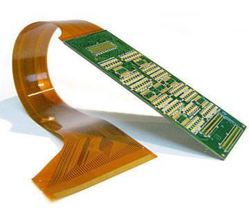
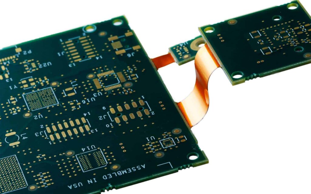
A rigid-flex PCB combines rigid PCB substrates with flexible PCB substrates. This allows the PCB to bend and flex in certain areas while maintaining rigidity in others. Here are the two main components of a rigid-flex PCB:
Rigid Sections – Made of typical rigid PCB substrates like FR-4, these provide structure and stability. Components are mounted and soldered here.
Flexible Sections – Made of polyimide or other flexible polymers, these allow the PCB to bend and fold. Minimal components are placed here.
By integrating both rigid and flexible materials, rigid-flex PCBs provide the benefits of both while minimizing limitations. They are ideal for products that require dynamic movement, compact form factors, or Embedded Help
Why Use Rigid-Flex PCBs?
Here are some of the top advantages that rigid-flex PCBs have over rigid PCBs:
- Space savings: Rigid-flex PCBs allow for more compact product designs by folding and bending to fit in tight spaces. This is critical for smaller handheld devices.
- Flexibility: Dynamic components like hinges and moving joints can be easily incorporated with flex regions. Rigid sections provide stability for mounting essential components.
- Reliability: Traces in flexible sections absorb stresses from motion that would cause breakage on rigid boards. This improves reliability and product life.
- Weight reduction: By condensing PCB size, rigid-flex PCBs weigh less than having multiple rigid PCBs in a product. This lightens portable devices.
- Simplified assembly: Using a single rigid-flex PCB allows for easier, streamlined assembly vs. connecting individual rigid PCBs.
- Cost efficiency: Despite higher individual PCB cost, rigid-flex PCBs lower overall system cost by enabling space savings and simpler assembly with fewer interconnects.
In summary, rigid-flex PCBs balance flexibility with rigidity to enable smaller, lighter, and more reliable electronic products. Their unique combination of properties make them perfect for compact portable devices.
Common Applications of Rigid-Flex PCBs
Here are some of the products and applications where rigid-flex PCBs are commonly used:
Consumer Electronics
- Cell phones
- Laptops
- Digital cameras
- Wearable devices
- Tablets
- Game controllers
Medical Devices
- Hearing aids
- Blood glucose monitors
- Infusion pumps
- Surgical tools
Industrial
- Robotics
- Automation equipment
- IoT devices
- Control systems
Aerospace
- UAVs and drones
- Avionics equipment
- Satellite systems
Automotive
- Navigation systems
- Dashboard displays
- Onboard computers
- EV battery systems
Any application where small size, dynamic bends, or high reliability are required can benefit from using rigid-flex PCBs over standard rigid PCBs.
Rigid-Flex PCB Design Considerations
Designing a successful rigid-flex PCB requires special considerations for the flex areas and rigid-flex transitions. Here are some best practice design tips:
Component Placement
- Minimize components in flex areas to just interconnects. Place them in rigid sections instead.
- Avoid placing components close to rigid-flex transitions.
- Anchor components near transitions using adhesive or fasteners to reduce stresses.
Trace Routing
- Use curved, rounded traces in flex regions instead of 90° angles.
- Leave adequate space between traces in flex areas.
- Add teardrop shapes at trace corners to reduce likelihood of cracks.
Layer Stacking
- Use thinner dielectrics between layers for optimal flexibility.
- Minimize the number of copper layers in flex regions.
- Ensure good registration between flexible and rigid layers.
Rigid-Flex Transition
- Allow sufficient room for flex material to bend without damaging rigid areas.
- Avoid 90° bends; use rounded, chamfered transitions instead.
- Utilize special corner reinforcement structures for added support.
Following these guidelines will ensure your rigid-flex PCB can withstand the demands of dynamic bending and folding expected in end products.
Rigid-Flex PCB Materials and Construction
Rigid-flex PCBs integrate different materials for the rigid and flexible substrates. Here are some of the most common options:
Rigid Substrate Materials
- FR-4: Most common rigid PCB material; familiar to manufacturers
- Polyimide: More expensive but better high temp performance than FR-4
- Aluminum: Used when high strength and heat dissipation are required
Flexible Substrate Materials
- Polyimide: Low cost and widely used for consumer electronics
- Fluoropolymer: Extremely flexible even in thin films, excellent chemical resistance
- LCP: High performance polymer, resistant to humidity and solders
Bonding Layers
- Acrylic adhesive: Most common method, bonds layers with adhesive film
- Thermal bonding: Uses high temperature melting to fuse layers
- Solvent bonding: Dissolves surfaces to fuse layers; leaves no adhesive residue
The substrates and bonding methods can be combined as needed to achieve the desired mechanical characteristics.
Rigid-Flex PCB Manufacturing Processes
Specialized fabrication techniques are required to manufacture rigid-flex PCBs, which differ from processes used for rigid PCBs. Here is an overview:
- Photolithography: Creates copper traces on individual flexible and rigid layers
- Laser drilling: Forms microvias to connect layers
- Lamination: Aligns and bonds rigid and flex layers using adhesive
- Contour milling: Cuts outline of PCB including any chamfers
- Coverlay attachment: Applies solder mask and markings for protection
- Final testing: Verifies electrical connectivity and performance
Rigid-flex PCBs require very careful layer-to-layer alignment and bonding to avoid any misregistration during bending. Most rigid-flex PCBs also utilize microvias rather than through-hole vias due to the thin flexible layers.
Rigid-Flex PCB Design Software Tools
Specialized PCB design software is available that can simplify the process of laying out a complex rigid-flex board. Here are some of the capabilities to look for:
- Handles both rigid and flexible substrates
- Allows trace routing across flex boundaries
- Includes rigid-flex templates and shapes
- Automated panelization and assembly planning
- Generates accurate 2D documentation and models
- Features interactive 3D visualization of rigid-flex PCBs
- Provides detailed system-level co-design features
- Supports DFx analysis for manufacturability
Using software designed for rigid-flex PCBs streamlines the design process and minimizes errors at each design stage. This can prevent costly re-spins and delays further along in the development cycle.
Rigid-Flex PCB Testing Considerations
Verifying the reliability of rigid-flex PCBs requires specialized testing tailored to their unique properties:
Flexure Testing: Validates trace integrity through repeated bending cycles
Torsion Testing: Checks for substrate fractures when subjected to twisting
Vibration Testing: Confirms component bonding and survival through vibration
Shock Testing: Determines robustness when exposed to drops or shock impacts
Temperature Cycling: Checks for any failures due to thermal expansion differences
Life Testing: Runs boards for extended durations to uncover potential field failures
With more variables than standard rigid boards, rigorous testing across environmental conditions is crucial to ensure reliable performance of rigid-flex PCBs once deployed.
Rigid-Flex PCB Assembly Considerations
In addition to design and fabrication, assembling components onto rigid-flex PCBs brings its own set of challenges:
Soldering Flexible Areas
Reflow soldering applies intense heat that can damage flexible substrates. Alternative soldering options for flex sections include:
- Hand soldering: Tedious but avoids subjecting flex areas to reflow temperatures
- Laser soldering: Focused heat minimizes thermal impact on flexible regions
- Solder jet printing: Selectively deposits solder only on target pads with no blanket heating
Flex Folding and Shaping
The flexible sections must be carefully bent and folded into the intended product shape. Fixtures and tools are used to avoid damaging the PCB during this process.
Managing Flex Stresses
Components anchored near rigid-flex transitions require adhesives or fasteners to minimize stresses from motion that could cause solder joint cracking.
Patterning and Cutting
Flexible tails need thorough cleaning between solder mask, markings, and V-scoring or routing to facilitate final detachment.
With each assembly step addressed, the fragile nature of the flex regions is less likely to impact quality and throughput.
Rigid-Flex PCB Assembly Equipment
Automated assembly systems designed for rigid PCBs may require modifications to properly handle rigid-flex boards without causing damage such as:
- Flexible feeders: Adjustable rails allow flexible sections to bend during conveyance
- Flex clamps: Secures PCBs while avoiding over-compression of flex areas
- Press-fit tools: Depth controlled to prevent crushing flexible layers
- AOI inspection: Improved handling fixture and algorithms for verifying flex region post-soldering
- Laser depaneling: Programmed cut paths separate boards along rigid/flex boundaries
While representing a notable investment, assembly equipment engineered for rigid-flex PCBs pays for itself through higher yields, less rework, and avoiding costly field failures.
Rigid-Flex PCB Applications in Electronics
With their unique combination of rigidity and flexibility, rigid-flex PCBs enable electronics manufacturers to create products with new industrial designs, functions, and user experiences. Here are some examples across consumer and commercial applications:
Cell Phones
Modern smartphones commonly utilize rigid-flex PCBs to integrate the main PCB with display and camera modules in a compact, folded configuration. High-end phones may also add flex sections to route signals to additional side or back displays and antenna arrays.
Laptops
Laptops need to balance connectivity, performance, and mobility. Rigid-flex PCBs allow squeezing more computing power into slimmer, lighter chassis by folding around tight corners and spaces. Hinged areas also benefit from flex circuits.
Digital Cameras
Fitting powerful image sensors, processors, storage, and displays into small cameras is enabled by rigid-flex PCBs that can curve around the interior perimeter. The boards bring together components mounted on both sides.
Hearing Aids
Tiny hearing aids easily fit in the ear canal thanks to rigid-flex PCBs that integrate tightly spaced components while still folding into ergonomic shapes. The flexible substrates also provide reliability with constant flexing.
Automotive Sensors
Sensors for airbags, tire pressure, engine monitoring, and collision detection require environmental durability and signal integrity. Rigid-flex PCBs survive vibration while routing signals from disparate points.
Medical Instruments
Devices like endoscopes and catheters benefit from rigid-flex PCBs that can navigate tight bends in the body while locates sensors or instruments at the end of the flexible tail for minimally invasive diagnostics and surgery.
This wide range of applications highlights why rigid-flex PCBs are becoming the go-to solution when reducing size, adding flexibility, and enhancing reliability are design priorities. As electronic devices continue getting smaller and more portable, adoption of rigid-flex PCB technology will keep increasing.
Rigid-Flex PCBs – Frequently Asked Questions
Here are answers to some common questions about rigid-flex PCB technology:
What are the typical layer counts for rigid-flex PCBs?
- Rigid sections usually contain 2-12 layers depending on component density and routing needs
- Flexible sections typically have 1-4 layers to maintain bendability
What are some suitable materials for rigid-flex PCB substrates?
- FR-4, polyimide, aluminum and LCP are commonly used for rigid sections
- Polyimide and fluoropolymers like Rogers and Polyflon are standard flexible dielectrics
Can components be mounted directly on flexible PCB sections?
Minimal components are recommended on flex areas. Only low-profile interconnects or passives should be added to avoid cracking during bending.
What are some methods for joining rigid and flex PCB substrates?
Adhesive films, thermal bonding, and chemical solvent bonding are three approaches used to laminate rigid and flex layers.
What are some key considerations when designing rigid-flex PCBs?
Trace routing, layer stacking, managing rigid-flex transitions, and component placement require special design considerations for rigid-flex PCB layout.
How are components assembled onto rigid-flex boards?
Reflow soldering can only be used selectively in rigid areas. Hand soldering, laser soldering or solder jet printing are alternatives for flexible sections.
Conclusion
Rigid-flex PCBs provide the small footprint, dynamic flexibility, and rugged reliability needed in modern electronic devices ranging frommobile gadgets to medical equipment. While requiring special design and assembly considerations, the benefits of integrating rigid and flexible materials into a single PCB substrate are driving increasing adoption across many industries. As electronics continue trending toward smaller, smarter, and more interconnected devices, rigid-flex PCB technology will play a key enabling role thanks to its unique set of advantages.


Leave a Reply