What is PCB Assembly Flexible?
Printed circuit board (PCB) assembly is the process of soldering electronic components to a PCB. PCB assembly flexible refers to assembling components on flexible PCB substrates rather than traditional rigid substrates.
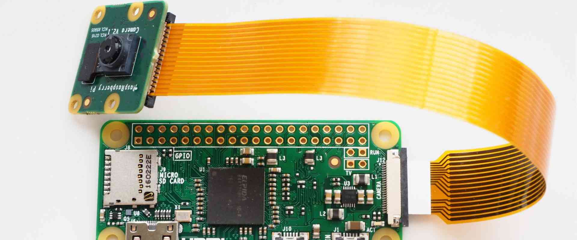
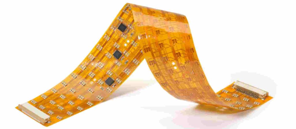
Flexible PCBs, also known as flex circuits, are made of flexible dielectric materials such as polyimide. They can bend, fold, and flex while still maintaining their electrical connectivity. Flexible PCBs are ideal for electronic devices with moving parts or limited space, like wearables, medical devices, and consumer electronics. They allow circuitry to fit into tight or dynamic spaces.
Benefits of Flexible PCB Assembly
Flexible PCB assembly provides several advantages over rigid PCB assembly:
- Adaptability: Flex circuits can take any shape and be manipulated to fit product requirements. This adaptability suits the complexity of emerging electronic devices.
- Durability: Flexible substrates are extremely durable and can withstand repeated bending. Rigid PCBs are prone to cracking under flexing stress.
- Lightweight: Flexible PCBs use thinner, lighter material than their rigid counterparts. This allows for lighter end products.
- Thinness: Flex circuits can be extremely thin, under 0.05 mm. Thinness suits small product enclosures and miniaturization trends.
- Reliability: Flexible PCBs offer reliable connectivity even in dynamic situations involving vibration, shocks, or moving parts.
- Cost efficiency: Flexible PCBs may cost less than rigid PCBs, especially in simpler, low-volume applications.
In summary, flexible PCB assembly provides size, weight, cost, and reliability benefits for modern electronic devices. The adaptability of flex circuits suits emerging technology needs.
Flexible PCB Materials
The main material components of a flexible PCB are:
- Flexible dielectric: The base material that forms the substrate. Common options are polyimide, polyester, transparent conductive polyester, and PEEK.
- Conductive layers: Usually copper foil. Other options include aluminum, gold, and silver.
- Bonding adhesive: Joins the conductive foil layers to the dielectric. Options include acrylic, phenolic butyral, epoxy, or modified acrylic.
- Coverlay: A protective coating over the top conductive layer. Common options are solder mask, coverlay composite, and elastomers.
Here are some details on the most common flexible PCB dielectrics:
- Polyimide: Kapton is a well-known brand of polyimide film. Polyimide offers high flexibility, temperature resistance, and chemical resistance.
- Polyester: Offers good flexibility and dielectric properties. Polyester is less expensive than polyimide but also less heat-resistant.
- Transparent conductive polyester: Allows for transparent flex circuits. This material has excellent optical clarity.
- PEEK: A high-performance polymer with excellent mechanical and thermal properties. PEEK is very durable.
Manufacturers select PCB materials suited to the product specifications, manufacturing process, and end use.
Types of Flexible PCBs
There are several classifications of flexible PCBs:
Single-Sided Flexible PCBs
Single-sided flex PCBs have conductive traces on one side of the dielectric substrate. The traces are often covered by a protective solder mask. Single-sided flex PCBs represent the simplest and most cost-effective flex circuit option.
Double-Sided Flexible PCBs
Double-sided flex PCBs have conductive traces patterned on both sides of the substrate. Vias connect the traces electrically through the dielectric. This provides more connection options than a single-sided board.
Multilayer Flexible PCBs
Multilayer flex PCBs contain three or more conductive layers separated by dielectric material. Complex flex PCBs can have up to 50 layers. However, 4-6 layers are typical. Multilayer boards offer increased component density and connection options.
Rigid-Flex PCBs
Rigid-flex PCBs combine standard rigid PCB sections with flexible PCB sections. They contain both rigid and flexible dielectric materials on the same board. Rigid-flex PCBs provide a seamless transition between rigid support structures and dynamic flexing interconnections.
Flexible PCB Design Considerations
Designing a flexible PCB requires special considerations:
- Bend radius: Avoid sharp folds by maintaining the minimum bend radius specified for the dielectric material. Sharp bends put excessive strain on traces.
- Trace spacing and width: Flexible PCBs require different trace characteristics than rigid boards to accommodate flexing.
- Layer stackup: Ensure adequate bonding adhesive between layers and verify component clearances.
- Component selection: Components must withstand flexing environments. Avoid large, heavy SMT parts.
- Board stiffness: Balance stiffness for manufacturing processes against flexibility for end use. Stiffeners or covers may be needed.
- ESD protection: Flexible PCBs require shielding and ground planes to protect against electrostatic discharge.
Proper flexible PCB design avoids common issues like cracking, delamination, component detachment, and broken interconnects.
Flexible PCB Assembly Process
Flexible PCB assembly follows these key steps:
1. SMT Component Placement: Surface mount devices are accurately placed onto PCB pads using automated pick-and-place machines.
2. Reflow Soldering: The PCB passes through a reflow oven to melt solder and attach components.
3. Post-Solder Cleaning: Removes flux residue from the soldering process.
4. Conformal Coating: A protective coating is applied over the assembled PCB.
5. Programming: Programmable devices are configured by programming firmware.
6. Testing and Inspection: Confirms assembly quality and functionality. Testing methods include in-circuit testing, flying probe testing, and automated optical inspection.
7. Singulation: Individual PCBs are cut or routed apart from the panel.
Flexible PCB assembly uses the same SMT assembly process as rigid PCBs but must account for the fragile materials. Handling panels without damaging flex PCB sections is an important consideration.
| Assembly Step | Key Considerations for Flexible PCBs |
|---|---|
| SMT Component Placement | Avoid placing heavy components in flexing areas. Adjust vacuum pressure during pick and place. |
| Reflow Soldering | Ensure temperature profiles suit flex PCB materials to prevent damage. Use thermocouples to monitor flex section temperatures. |
| Cleaning | Select cleaning agents compatible with flexible PCB materials. Clean thoroughly to avoid conductor corrosion. |
| Conformal Coating | Apply coating properly to prevent flex PCB damage during bending. Select a coating compatible with flexing. |
| Testing | Fixture boards to avoid damaging flex sections during in-circuit test. Perform functional testing while flexed. |
| Singulation | Use proper blade depth, pressure, and angle to avoid scratches and copper burrs. |
Flexible PCB Assembly Challenges
While having excellent benefits, flexible PCBs also come with unique assembly challenges:
- Fragile substrates: Flexible PCB materials are thin, delicate, and prone to scratches or tears. This demands careful handling during assembly.
- Dimensional stability: Flexible PCBs can shrink, warp, or change shape during soldering if not properly stabilized.
- Creep: Flexible materials slowly move and change shape under constant load and temperature over time. This affects long term reliability.
- Limited real estate: Flexible PCBs offer less surface area than rigid boards, constraining component selection and density.
- Thermal management: Flexible PCBs dissipate heat less effectively than rigid boards. Heat accumulates in flexing areas.
- ESD protection: Static charges can damage components on flex PCBs without proper grounding.
- Inspection complexity: Automated optical inspection cameras have a limited depth of field, making inspection of uneven flex PCBs more difficult.
- Via reliability: Plated through holes are prone to cracking on dynamic flex PCBs.
Careful process engineering and control is needed to manage these challenges and assemble reliable flexible PCBs.
Applications of Flexible PCB Assemblies
Due to their unique benefits, flexible PCB assemblies are used across many industries:
- Wearable technology: Fitness trackers, smart watches, health monitors, etc. Flex PCBs can conform to wrists and arms.
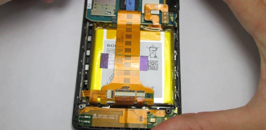
- Consumer electronics: Cell phones, cameras, video game controllers, etc. Allows circuitry to fit into tight, crowded casings.
- Automotive: Flex circuits integrate into dynamic automotive subsystems like steering, brake lines, sensors, etc.
- Medical: Hearing aids, pacemakers, patient monitoring devices. Suits curvy surfaces and complex shapes.
- Military: Missile guidance systems, radars, communications, wearables. Rugged and reliable in demanding environments.
- Robotics: Flexible interconnections for joints, arms, grippers, rotors. Withstands repeated bending motions.
- Avionics: Flight control systems, engine monitors, in-flight entertainment. Lightweight for airborne applications.
As electronic devices become smaller, more powerful, and more dynamic, flexible PCB assemblies provide interconnectivity solutions not possible with rigid boards.
Finding a Flexible PCB Assembly Partner
Choosing the right contract manufacturing partner is key to successful flexible PCB assembly. Here are important capabilities to look for:
- Flexible PCB fabrication experience: Look for expertise in the materials, stacking, and trace characteristics unique to flex PCBs.
- Engineering collaboration: Find a partner willing to work closely with your engineers to optimize the design for manufacturing and reliability.
- Quality certifications: Ensure the CM follows rigorous quality systems. Look for ISO 13485 medical certification if making medical devices.
- Flexible assembly expertise: The CM should have experience managing the intricacies and challenges of assembling fragile flex PCBs.
- Volume scalability: Look for capabilities supporting low to mid volume production. Avoid very high volume, low-mix vendors.
- Robust supply chain: The CM should maintain approved supplier lists and component inventory to avoid shortages.
- Testing capabilities: Thorough testing like ICT, flying probes, and burn-in helps ensure the reliability of flex assemblies.
With an experienced, collaborative manufacturing partner, companies can harness the advantages of flexible PCB technology and overcome the unique assembly challenges.
Frequently Asked Questions
Q: What are some key design differences between rigid and flexible PCBs?
A: Flexible PCBs require different trace spacing, widths, and stackups to accommodate dynamic bending. They also need special considerations around bend radius, component selection, and layer materials. Stiffeners may be required on flex boards while they would interfere with rigid board performance.
Q: What materials are commonly used for flexible PCB substrates?
A: The most common dielectric materials for the flexible substrate are polyimide films (like Kapton), transparent conductive polyester, polyester films, and PEEK. Polyimide is generally considered the highest performance option.
Q: How many conductive layers can you get on a flexible PCB?
A: Flexible PCBs are available in single sided, double sided, and multilayer configurations. Complex flexible PCBs can have up to 50 conductive layers, however 4-6 layers are more common. Two-layer flex boards provide the best cost and performance balance for many designs.
Q: What are some examples of rigid-flex PCB applications?
A: Rigid-flex PCBs are ideal when a design needs dense, complex circuitry combined with dynamic flexing capability. Common examples include foldable cell phones, wearable devices, and medical electronics like endoscopes where flex sections connect the rigid PCBs.
Q: Are surface mount or through-hole components more common for flexible PCB assembly?
A: Surface mount components are overwhelmingly more common on flex PCB assemblies. SMT packages take up less space and withstand flexing environments better than through-hole components. However, some connectors or pins may use through-hole attachment.
Final Thoughts
Flexible PCB technology provides interconnectivity solutions not possible with traditional rigid boards. As electronic products become increasingly complex within tighter spaces and added flexibility, flex PCB assembly offers an enabling technology. When combined with an experienced manufacturing partner, companies can effectively apply flexible PCB assemblies across a wide range of industries and applications.


Leave a Reply