Introduction
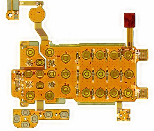
Flexible printed circuit boards (flex PCBs) have become an increasingly popular solution for electronic devices where flexibility, space savings, or durability are required. Heavy copper flex PCBs offer improved performance compared to standard flex circuits by using thicker copper layers. This allows for higher current capacity, improved heat dissipation, and lower resistance.
In this article, we will examine the benefits of using heavy copper in flexible PCB designs, the typical specifications, and applications that can benefit from this technology. We will also look at design considerations when working with heavy copper flex circuits.
What are Heavy Copper Flex PCBs?
Standard flex PCBs use 1⁄2 oz (17 μm) or 1 oz (35 μm) copper thickness on the conductive layers. Heavy copper flex PCBs use thicker copper foil, typically 2 oz (70 μm) or 3 oz (105 μm). This provides several advantages:
- Higher current carrying capacity. The thicker copper can handle more current flow with less resistive losses and heating.
- Improved thermal performance. The thicker metal layers conduct heat better, spreading heat over a larger surface area.
- Lower resistance. With more cross-sectional copper area, heavy copper flex has lower electrical resistance.
- Stronger traces. Thicker copper foil is mechanically more durable and resistant to fracturing or damage.
- Fewer layers possible. The increased current per layer may allow using fewer layers for some designs.
The key tradeoff is that increasing the copper thickness also increases the overall flex PCB thickness. The flex circuit becomes stiffer and less flexible with more copper. So heavy copper is most applicable for designs where at least some minimum bend radius is acceptable.
Heavy Copper Flex PCB Specifications
Here are some typical specifications for heavy copper flex PCBs:
- Copper thickness: 2 oz (70 μm) and 3 oz (105 μm) are common
- Current capacity: Up to 5-10X higher than 1 oz copper foil
- Bend radius: Minimum bend radius typically increases with copper thickness
- Dielectric thickness: Additional dielectric layers may be needed to cover thicker copper
- Flexibility: Heavy copper flex is stiffer than standard 1 oz boards
- Layer count: Performance gains allow some designs to use fewer layers
The increased thickness does present some fabrication challenges. Special processing techniques may be needed to properly adhere the thicker copper and prevent delamination.
Applications for Heavy Copper Flex Circuits
Here are some examples of products and applications that can benefit from the use of heavy copper flexible PCBs:
High Current Flex Circuits
The higher current capacity makes heavy copper a good choice for power distribution, power conversion, and other high current applications such as:
- Power supply flex circuits
- LED lighting flex circuits
- Battery/energy storage interconnects
- Motor/actuator control flex
Flexible Heaters
The excellent thermal conductivity allows heavy copper flex PCBs to be used as heating elements. Applications include:
- Flexible heaters for industrial and consumer products
- Defrost heaters in HVAC systems
- Medical warming devices
- Automotive circuit heating
EMI Shielding
The thicker copper provides more effective electromagnetic shielding from interference. Uses include:
- EMI shielding in medical,aerospace, and telecom equipment
- Noise reduction in high frequency circuitry
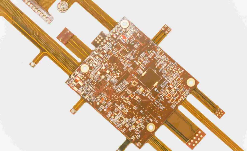
Flex-to-Board Interconnects
Heavy copper flex PCBS work well for board-to-board and board-to-component interconnects that require high current capacity and low resistance across the flex section.
Design Considerations for Heavy Copper Flex Circuits
Here are some important design factors to consider when working with heavy copper flex PCBs:
Bend Radius
The minimum bend radius increases as the copper gets thicker. For 90° bends, here are typical minimum inside bend radii:
- 1 oz copper: 0.125 in (3.2 mm)
- 2 oz copper: 0.1875 in (4.8 mm)
- 3 oz copper: 0.25 in (6.4 mm)
For dynamic or rolling flex applications, even larger bend radii are required.
Conductor Width and Spacing
With thicker copper, trace widths and spacing may need adjustment. Wider traces are generally needed to handle higher currents. The increased layer thickness also impacts spacing requirements.
Layer Stackup and Dielectrics
Additional dielectric layers may be incorporated to completely cover heavy copper layers. Polyimide is a common flexible dielectric. Adhesive types used in multilayer constructions should be selected to withstand flexing.
Stiffness and Flexibility
While heavy copper flex PCB can still be bent, the circuit will be stiffer than standard flex. This stiffness needs to be considered against the required flexing performance. Some designs may need selective patterning or removal of copper to improve flexibility in certain areas.
Fabrication Considerations
Heavy copper processing requires specialized methods to handle the thicker foils. Etching, bonding, and drilling may need adjusted parameters. Working with an experienced flex PCB manufacturer is advised.
Thermal Management
The improved thermal performance of heavy copper requires less cooling overhead. However, designers should still use techniques like thermal reliefs and copper balancing on inner layers. Thermal modeling is recommended.
Conclusion
Heavy copper flexible PCBs provide higher current capacity, better cooling, lower resistance, and improved reliability compared to standard thin copper flex circuits. These benefits make heavy copper a good choice for high power flex applications such as power supplies, motor controls, heaters, and high-frequency shielding. With careful design consideration for parameters like minimum bend radius, trace width, and layer stackup, heavy copper flex PCBs can improve performance in many products requiring flexible circuitry.
Frequently Asked Questions
Q: What are the typical copper weights used in heavy copper flex PCBs?
A: The most common heavy copper weights are 2 oz (70 μm) and 3 oz (105 μm). Some manufacturers also offer 1.4 oz (50 μm) as a lighter high current option. The increased copper thickness improves current capacity, cooling, and reliability.
Q: What are the limitations of heavy copper flex circuits?
A: The main limitations are decreased flexibility and bendability as copper weight increases. Heavy flex PCBs should only be used where an acceptable minimum bend radius is possible for the application. The thick copper also increases overall circuit thickness.
Q: How are heavy copper layers bonded in multilayer flex PCBs?
A: Adhesive systems designed for flex PCBs must be used, typically acrylic, epoxy, or polyimide adhesives. Proper adhesion is critical to prevent cracking or delamination, especially on inner layers. Fabricators optimize bonding processes for heavy copper.
Q: When does it make sense to use heavy copper versus standard 1oz foil?
A: Heavy copper should be considered when higher current capacity, lower resistance, better cooling, or longer flex life are critical performance factors. The higher cost of heavy copper is justified for demanding high-power flex applications.
Q: What are important design considerations for trace routing on heavy copper flex?
A: Wider traces are needed for higher currents. Adequate spacing should be provided based on dielectric thickness. Lightning shaped traces can help minimize stiffness. Selective patterning or buildup can maintain maximum flexibility where needed.


Leave a Reply