Introduction to Hartley Oscillators
Hartley oscillators are a type of electronic oscillator circuit that uses a resonant circuit consisting of an inductor and capacitor to produce a sinusoidal output waveform. They are named after American engineer Ralph V.L. Hartley who invented the design in 1915 while working at Western Electric.
The key advantage of Hartley oscillators is their ability to maintain a constant amplitude output signal even with variations in the load impedance or supply voltage. This makes them ideal for applications requiring a stable frequency reference such as in radio transmitters, signal generators, and electronic test equipment.
How Hartley Oscillators Work
The basic circuit of a Hartley oscillator consists of an amplifier stage with the output fed back to the input through a resonant LC tank circuit. The tank circuit determines the frequency of oscillation and also provides the necessary phase shift for positive feedback to occur, allowing the circuit to produce sustained oscillations.
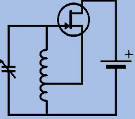
Here is a simplified schematic of a typical Hartley oscillator:
            +Vcc
             |
            +-+
            | |
            | |  L1
            | |  +---+---+
            +-+  |   |   |
             |   |   |   |
            +-+  |  C1   |
            | |  |   |   |
            +-+  +---+---+
             |      |
            +-+     |
            | |    +-+
           |/  C2 |/  R1
    Vout---|- Q1  |- Q2
           |\     |\
            +-+    +-+
             |      |
            ///    ///
In this circuit, Q1 and Q2 form a common emitter amplifier stage with the LC tank connected between the collector of Q1 and ground. Capacitor C2 provides the necessary coupling between the collector of Q1 and the base of Q2 to create positive feedback. Resistor R1 sets the bias current for Q2.
The resonant frequency of the tank circuit is given by:
$$ f = \frac{1}{2\pi\sqrt{LC}} $$
Where L is the inductance of L1 and C is the series combination of C1 and any Stray Capacitance. The inductance is usually provided by a tapped coil which also determines the feedback ratio. The tap point is chosen to provide the optimal trade-off between loop gain and output amplitude while ensuring reliable starting.

Advantages of Hartley Oscillators
Compared to other oscillator topologies like Colpitts and Clapp, Hartley oscillators have several advantages:
-
Simplicity – Hartley oscillators require fewer components than other designs making them easy to build and troubleshoot. The tapped coil can be easily adjusted to set the desired frequency.
-
Wide Frequency Range – By using a variable capacitor for C1, Hartley oscillators can be tuned over a wide frequency range, typically 10:1 or greater. This makes them suitable for variable frequency applications.
-
Good Frequency Stability – The frequency determining elements (L1 and C1) are isolated from the active device, minimizing the effect of variations in transistor parameters with temperature or aging. The high Q of the tank circuit also helps to reduce phase noise.
-
Constant Amplitude – The amplitude of oscillation is determined by the non-linear characteristics of the transistor and the feedback ratio set by the tap on L1. This allows the amplitude to remain constant despite changes in load or supply voltage.
-
Efficient – Hartley oscillators can achieve high efficiency, especially when operated in Class C mode where the transistor conducts for less than half of the cycle. This minimizes power dissipation in the transistor and improves battery life in portable equipment.

Applications of Hartley Oscillators
Hartley oscillators are used in a wide variety of electronic systems wherever a stable, low-noise frequency reference is required. Some common applications include:
RF Transmitters
Hartley oscillators are often used as the local oscillator (LO) in radio transmitters to generate the carrier frequency. The output of the oscillator is typically buffered and amplified to the desired power level before being applied to the antenna. In some designs, the oscillator may be modulated directly to produce FM or PM signals.
Signal Generators
Bench top and handheld signal generators use Hartley oscillators as the core frequency source. The oscillator is followed by a variable attenuator and output amplifier to provide an adjustable signal level. Analog signal generators may use a varactor diode for C1 to allow voltage controlled tuning, while digital versions use a frequency synthesizer locked to a crystal reference.
Tracking Generators
Spectrum analyzers and network analyzers often include a tracking generator which is a swept frequency source that follows the tuned frequency of the receiver. Hartley oscillators are well suited for this application due to their wide tuning range and constant output amplitude.
Proximity Sensors
Hartley oscillators can be used as proximity sensors by using the target object as part of the tank circuit. As the object approaches the sensor, it alters the inductance or capacitance, causing the oscillation frequency to change. This change can be detected and used to trigger an alarm or control a process.

Designing Hartley Oscillators
When designing a Hartley oscillator, there are several key factors to consider:
Frequency Range
The desired frequency range will determine the values of L1 and C1 as well as the type of variable capacitor required. For wide band VFOs, a multi-section air variable capacitor is often used. For fixed frequency operation, a combination of fixed capacitors and a trimmer may be used.
The inductance of L1 should be chosen to give a reasonable value of C1 for the desired frequency. Too small of an inductance will result in a large value of C1 which may be impractical or have too low of a Q factor. Conversely, too large of an inductance will require a very small value of C1 which may be difficult to control.
As a starting point, aim for a reactance of around 1k at the operating frequency for both L1 and C1. This will ensure a reasonable Q factor and manageable component values.
Tapping Point
The location of the tap on L1 sets the feedback ratio and affects both the loop gain and output amplitude. Moving the tap closer to the collector of Q1 increases the feedback and lowers the output impedance, while moving it closer to ground reduces the feedback and increases the output impedance.
A good starting point is to place the tap at around 1/3 of the total turns from the ground end of L1. This provides a reasonable compromise between output level and stability. The exact location can then be optimized experimentally for the desired performance.
Transistor Selection
The choice of transistor for Q1 and Q2 is not critical but some general guidelines apply. The transistor should have a high enough frequency response to ensure reliable starting and low phase noise. The collector-emitter breakdown voltage should be at least twice the supply voltage to allow for voltage swings across the tank circuit.
Bipolar junction transistors (BJTs) are most commonly used but field effect transistors (FETs) can also be used, especially at VHF and higher frequencies. For battery powered equipment, low power devices are preferred to minimize current consumption.
Some suggested transistors for various frequency ranges are:
| Frequency Range | Transistor Types |
|---|---|
| < 1 MHz | 2N3904, 2N3906, BC547, BC557 |
| 1 – 10 MHz | 2N2222, 2N2907, BC337, BC327 |
| 10 – 100 MHz | 2N3563, 2N3866, BF199, BF200 |
| 100 – 1000 MHz | BFR90, BFR91, BFG135, BFG235 |
| > 1000 MHz | BFR520, BFR540, BFP420, BFP450 |
Of course, these are just examples and many other suitable devices are available. It’s always best to consult the manufacturer’s data sheets and application notes for specific recommendations.
Supply Voltage and Decoupling
Hartley oscillators are relatively insensitive to supply voltage variations but it’s still important to provide a clean, well-regulated source. Noise and ripple on the supply can modulate the oscillator and cause unwanted sidebands.
A simple LC or RC decoupling network should be used to filter the supply line. This can be a combination of a series inductor or resistor and a parallel capacitor connected close to the oscillator. The values are not critical but should be chosen to provide a low impedance at the operating frequency.
For example, a 10uH inductor and 100nF capacitor will provide over 30dB of attenuation at 1MHz while a 100 ohm resistor and 10nF capacitor will give similar performance at 10MHz.
PCB Layout
Proper PCB layout is essential for optimal performance of any RF circuit and Hartley oscillators are no exception. Some key points to consider are:
- Keep the tank circuit components (L1, C1) close together and away from other parts of the circuit. This minimizes stray capacitance and inductance which can affect the frequency.
- Use a ground plane under the oscillator section to provide a low impedance return path for the AC currents. This helps to reduce radiation and coupling to other stages.
- Provide adequate shielding around the oscillator, especially if it is used in a sensitive receiver. A metal enclosure or shield can may be necessary in some cases.
- Use short, direct traces for the feedback path from the emitter of Q2 to the tap on L1. Avoid running this trace near other high impedance nodes or traces carrying large currents.
- Decouple the supply voltage to the oscillator with a local LC or RC filter. Place this close to the collector of Q1 to minimize the loop area.
- If a variable capacitor is used for tuning, mount it securely to the PCB or chassis to avoid microphonics. Use short, stiff leads and provide strain relief for any wires or cables.
By following these guidelines, you can ensure your Hartley oscillator will provide the best possible performance and reliability.
Troubleshooting Hartley Oscillators
Despite their simplicity, Hartley oscillators can sometimes be tricky to get working properly. If your oscillator isn’t starting up or is producing an unexpected output, here are some things to check:
-
DC voltages – Verify that the transistors are biased correctly and that the collector voltage is approximately half the supply voltage. If the bias is too low, the transistors may not have enough gain to sustain oscillation. If the bias is too high, the transistors may saturate and cause distortion or spurious oscillations.
-
Component values – Double check that all components are the correct value and type. Pay particular attention to the polarity of electrolytic capacitors and the pinout of transistors. A misplaced component or incorrect value can prevent the oscillator from starting or cause it to operate at the wrong frequency.
-
Feedback phase – The feedback from the tank circuit to the base of Q2 must be in phase with the emitter signal for oscillation to occur. If the tap on L1 is in the wrong place, the feedback may be out of phase and cancel the oscillation. Try adjusting the tap location or reversing the connections to L1.
-
Tank circuit Q – The quality factor (Q) of the tank circuit determines how much energy is lost each cycle and affects the amplitude of oscillation. If the Q is too low, the oscillator may not start or may have a low output level. Check the quality of the inductor and capacitors and make sure there are no unwanted resistances or losses in the tank circuit.
-
Stray capacitance and inductance – At high frequencies, stray reactances can have a significant effect on the oscillator performance. Make sure the layout is tight and clean with minimal lead lengths. Use shielding and ground planes to minimize coupling to other parts of the circuit.
-
Loading effects – The load on the oscillator output can affect the frequency and amplitude of oscillation. Make sure the load impedance is much higher than the output impedance of the oscillator (typically a few kΩ). Use a buffer stage or impedance matching network if necessary to isolate the load from the oscillator.
By carefully checking each of these factors, you should be able to identify and correct any problems with your Hartley oscillator and get it working properly.
Frequently Asked Questions
1. What is the main advantage of a Hartley oscillator over other types?
The main advantage of a Hartley oscillator is its ability to maintain a constant amplitude output over a wide range of load impedances and supply voltages. This makes it well suited for applications requiring a stable, low-noise frequency reference.
2. How do you adjust the frequency of a Hartley oscillator?
The frequency of a Hartley oscillator is determined by the resonant frequency of the tank circuit, which is set by the inductance of L1 and the capacitance of C1. To adjust the frequency, you can either change the value of C1 (typically with a variable capacitor) or adjust the inductance of L1 (by changing the number of turns or the core material).
3. What is the purpose of the tap on the inductor in a Hartley oscillator?
The tap on the inductor (L1) provides the feedback signal from the tank circuit to the base of the second transistor (Q2). The location of the tap determines the amount of feedback and affects the loop gain and output amplitude. Moving the tap closer to the collector of Q1 increases the feedback, while moving it closer to ground decreases the feedback.
4. Can a Hartley oscillator be used at high frequencies (VHF and above)?
Yes, Hartley oscillators can be used at frequencies up to several hundred MHz with proper component selection and PCB layout. At VHF and higher frequencies, special attention must be paid to minimizing stray capacitance and inductance, as well as providing adequate shielding and grounding.
5. What type of transistor is best for use in a Hartley oscillator?
The choice of transistor is not critical but should have a high enough frequency response and gain to ensure reliable starting and low phase noise. BJTs are most commonly used but FETs can also be used, especially at higher frequencies. For battery powered equipment, low power devices are preferred to minimize current consumption.
Conclusion
Hartley oscillators are a simple and reliable way to generate a stable, low-noise frequency reference in a wide range of electronic applications. By understanding the basic principles of operation and following good design practices, you can easily build and troubleshoot Hartley oscillators for your own projects.
Remember to carefully consider factors such as frequency range, tapping point, transistor selection, and PCB layout when designing your oscillator. And if you run into problems, follow the troubleshooting steps to identify and correct any issues.
With their simplicity, wide frequency range, and constant amplitude output, Hartley oscillators are an excellent choice for many electronic systems requiring a stable frequency source. So why not give them a try in your next project?


Leave a Reply