Introduction to FR4 Flex Circuits
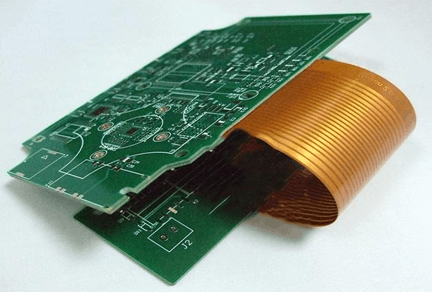
FR4 flex circuits, also known as flexible printed circuits (FPCs), are made from a dielectric base of FR4 material that is laminated with copper traces and connectors. The FR4 base provides the circuit with rigidity and structure, while the copper laminate allows for the routing of electrical signals. The circuit can be bent and flexed to accommodate unique form factors and moving parts without losing circuit continuity.
FR4 flex circuits provide a number of advantages over traditional rigid printed circuit boards (PCBs) due to their flexible nature. Some of the key benefits of FR4 flex circuits include:
Adaptability
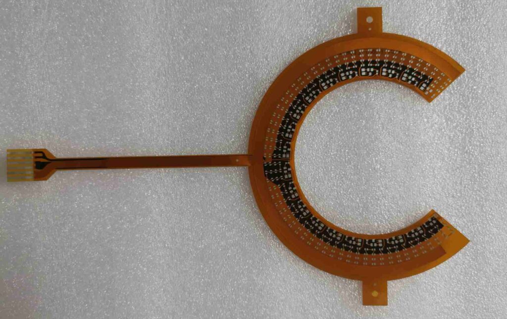
FR4 flex circuits can be bent, folded, and shaped to fit into tight spaces and moving parts where rigid boards cannot. This makes them ideal for complex and compact electronics like cell phones, wearables, medical devices, etc. The circuits can be dynamically flexed during use without cracking or failing.
Durability
The FR4 base material gives the flex circuit much more durability and tolerance compared to circuits made solely from flexible materials like polyimide film. FR4 flex can withstand vibration, shock, and repeated bending cycles better than purely flexible circuits.
Design Freedom
Because FR4 flex circuits can be manipulated into unique three-dimensional shapes, they provide more design freedom to engineers. Circuits can be sculpted to maximize space and component layout in complex devices.
Reliability
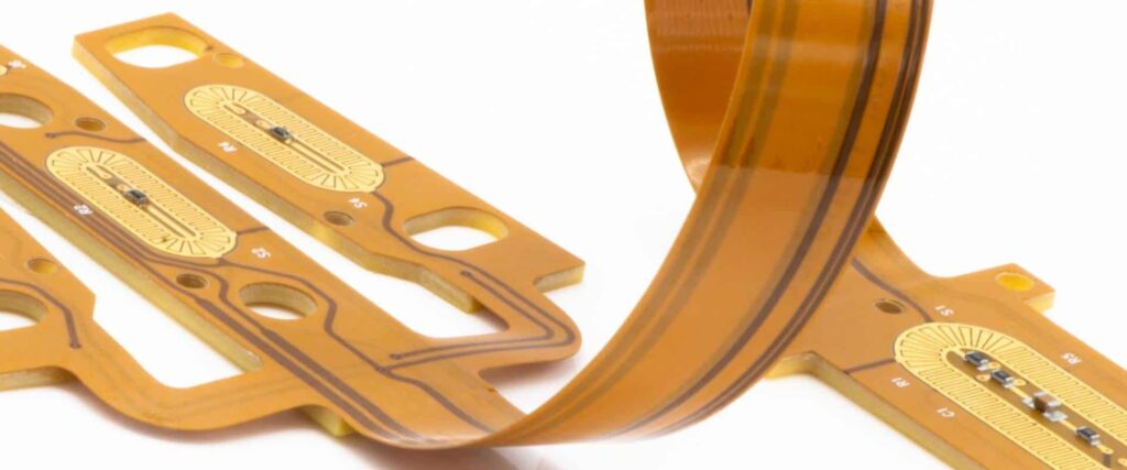
The laminated copper traces allow for reliable connectivity even when the circuit is subjected to dynamic bending forces. FR4 flex circuits have excellent circuit reliability and continuity even after thousands or millions of flex cycles.
Cost-Effectiveness
Using FR4 material as the flexible circuit base provides a good balance between cost and performance. FR4 flex offers better flex life and durability than polyimide film at a lower cost than materials like PTFE Teflon.
FR4 Flex Circuit Design Considerations
When designing a flex circuit with an FR4 base, there are some important factors to consider for optimal performance and reliability.
Bend Radius
The minimum bend radius for an FR4 flex circuit should be carefully calculated and followed to prevent cracking. Inside bend radii are typically 3-5X the circuit thickness for dynamic or moving bends. For static bends, 1-2X circuit thickness is acceptable.
Layer Stackup
The copper layer count and stackup design impacts the flex circuit’s bend radius and reliability. Common configurations are 4-8 copper layers, with 2 oz. copper thickness on the outer layers and 1 oz. on inner layers.
Stiffener Integration
Integrating stiffener components like boards, plates, or shields along with the flexible circuit helps manage the overall bending. Stiffeners prevent over-flexing and guide the dynamic bend radius.
Damaged Trace Mitigation
One reliability risk is damaged traces over continual flexing. This can be mitigated by using redundant traces, limiting sharp bends near connectors, and securing flex areas.
Flex/Rigid Transition
Transition areas between rigid sections like connectors and flexible sections are vulnerability points. The circuit layout should provide gradual transitions reinforced with solder mask.
Adhesive Selection
Choosing the right adhesive is critical for attaching the flex circuit to its housing while allowing dynamic bending motion. Ideal adhesives provide electrical isolation with some reworkability.
Popular Applications of FR4 Flex Circuits
Some of the most common applications that benefit from the advantages of FR4 flex circuit technology include:
Consumer Electronics
Cell phones, laptops, tablets, wearables, headphones, and other compact consumer electronics rely on flexible circuits to interconnect small form factor components. FR4 flex is durable enough for these demanding applications.
Automotive Electronics
Flex circuits withstand vibration while fitting into tight spaces, making them well-suited for automotive applications like sensors, engine control units, lighting, etc. The FR4 base also meets automotive temperature requirements.
Medical Devices
Medical device manufacturers use flexible circuits to connect sensors, tubes, pumps, leads through housings and maneuverable instrument arms for applications like robotic surgery and diagnostics.
Industrial Electronics
Industrial electronics like motor controls, PLCs, HMI panels, and robotics achieve reliability using flex circuits which stand up to continuous vibration and motion. Water-resistance is also a plus.
Consumer Appliances
Home appliances like microwaves, washers, thermostats, and printers package complex electronics in tight spaces which benefit from the use of durable, adaptable flex circuits.
Aerospace and Defense
Avionics, radars, flight control systems, and communications gear on aircraft, spacecraft, missiles, and satellites use flex circuits proven to withstand shock, vibration, temperature extremes.
FR4 flex circuits have become vital in these applications for packing more electronics reliably in ever-decreasing spaces. Engineers rely on the ruggedness and tight bend radii of FR4 flex to withstand millions of flex cycles over the product lifetime. The design freedom enables efficient layouts and component placement even in cramped enclosures.
Key Manufacturing Processes for FR4 Flex Circuits
Specialized manufacturing techniques are required to produce reliable FR4-based flex circuits in high volumes. Here are some of the essential fabrication processes:
Etching
The copper foil layers are etched to form the desired conductive traces and connection pads which carry power and signals. Photolithographic patterning with acid etchants is typically used.
Lamination
The etched copper foil layers are precisely aligned and laminated to the FR4 dielectric base using high heat and pressure. Adhesives permanently bond the layers.
Plating
Exposed copper traces are plated with immersion tin or other finishes to protect against oxidation and improve solderability. Hard gold plating is also applied to contact fingers.
Coverlay Addition
A thin polyimide coverlay layer is laminated over the flex circuit to provide electrical isolation and protect traces on the outer layers.
Via Formation
Mechanically drilled or laser-drilled vias electrically interconnect the conductive traces between layers. The vias are plated for conductivity.
Singulation
Individual flex circuits are cut or routed from the larger fabrication panel. This singulates the designs prior to component assembly.
With expertise in these specialized processes, flex circuit manufacturers can produce FR4-based designs optimized for the application requirements.
Assembly Considerations for FR4 Flex Circuits
There are some unique considerations when assembling components onto designed FR4 flex circuits compared to traditional PCBs:
- Components are typically only assembled on the rigid areas of the circuit, avoiding the flexible bend areas.
- Smaller surface mount devices are ideal. Care is required when handling to avoid cracking FR4 laminate.
- Flex circuits are fixtured during assembly to control the shape and avoid twisting or warping.
- Adhesives are used to strengthen component attachments in vibration/shock environments.
- Automated assembly robots have advanced handling features for fragile flex circuits.
- Consider fatigue life of solder joints and traces over flex cycles. Use of adhesives improves fatigue resistance.
- Inspection checks for cracked laminate traces, weakened solder joints, and fractured plated through holes.
With proper assembly methods, components can be reliably integrated onto the flex circuits. The populated circuits can then be integrated into the finished electronic devices.
Trends Driving Broader Adoption of FR4 Flex Circuits
Several technology and market trends are further accelerating the use of FR4 flex circuits over traditional wiring harness and rigid PCBs:
- Miniaturization of electronics demands dense, reliable interconnects.
- Growth of wearables, medical devices, and Internet of Things.
- Improved flex circuit CAD tools and modeling of bend stresses.
- Automation of flex circuit fabrication, allowing higher volumes.
- Increased electronics content in automotive, automation, aerospace.
- Focus on lighter, more efficient mechanical and electrical designs.
These trends are motivating manufacturers across markets to take advantage of the benefits of FR4 flex circuits within their electronic devices and machines. The technology provides a robust interconnect solution as electronics become more compact and complex.
Summary of Key Benefits
To summarize, here are the major benefits provided by FR4 flex circuits:
- Adaptability to fit and move within tight spaces
- Durability to withstand vibration, shock, and repeated bends
- Design freedom to sculpt circuits around components
- Reliability of trace connections during motion
- Cost-effectiveness for balance of cost and performance
As electronics applications continue requiring compact, robust interconnection, FR4 flex circuits provide an enabling technology to meet size, reliability, and cost requirements. With an industry leading bend radius and proven flex life, FR4 flex circuits deliver interconnectivity in demanding use cases spanning consumer wearables to commercial avionics. Careful design, manufacturing, and assembly of the circuits allows realizing their full potential across markets demanding next-generation electronics.
Frequently Asked Questions
What is the typical thickness of an FR4 flex circuit?
Typical FR4 flex circuit thicknesses range from about 0.5mm to 2mm. Thicker constructions provide more rigidity while thinner circuits maximize flexibility. 1mm thickness offers a good compromise for many designs.
What are some alternatives to FR4 material for flex circuits?
Other common flex circuit substrate materials are polyimide, PET, PEN, PID, and PTFE Teflon. Polyimide offers very high flexibility but lower rigidity than FR4. PTFE provides the best thermal/chemical resistance.
What are some ways FR4 flex can be integrated into devices?
FR4 flex circuits can be attached with adhesive, soldered, mechanically fastened with standoffs, or inserted into slots. Rigid sections allow straightforward mounting while flex areas accommodate motion.
What are some key factors impacting minimum bend radius?
Trace thickness, dielectric material, number of layers, copper vs. adhesive percentage, reinforcement materials, dynamic vs. static bending, and heat exposure affect minimum bend radius.
How many bend cycles can FR4 flex circuits withstand?
Well-designed FR4 flex circuits can endure over 1 million dynamic flex cycles. Factors like bend radius, trace design, and assembly impact fatigue life. Conservative design ensures long flex life.


Leave a Reply