Introduction
Flexible printed circuit boards, commonly known as flex circuits or flex PCBs, represent an exciting advancement in electronics design and manufacturing. As the name suggests, these boards utilize flexible substrate materials like polyimide rather than traditional rigid boards made of materials like FR-4. This flexibility allows for a variety of innovative form factors, applications and assembly methods that aren’t possible with rigid boards. In this comprehensive guide, we’ll explore what sets flexible PCBs apart, their design considerations, manufacturing processes, emerging applications and more. With the right understanding of their capabilities, flex circuits can be a game changer for products across industries.
What Are Flexible Printed Boards?
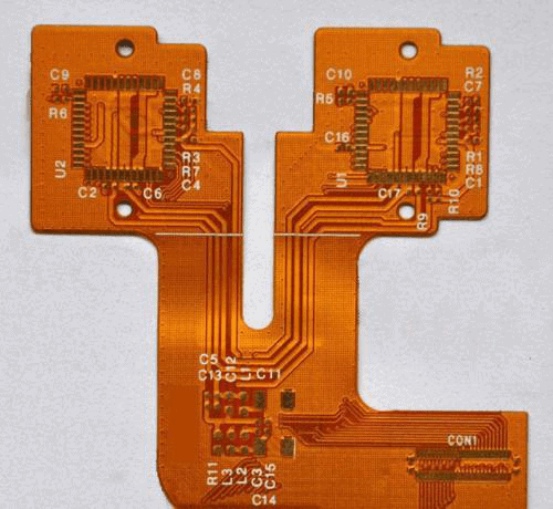
A flexible printed board or flex PCB utilizes a thin, bendable material as its base rather than a rigid board. Polyimide film is the most commonly used flexible substrate and offers excellent thermal stability and dielectric properties. Other materials like transparent conductive polyesters and parylene are also gaining popularity. The conductive traces are bonded to this flexible material through etching, screen printing or a photolithographic process. This allows the creation of complex circuits on a thin, bendable surface.
Flex PCBs can have one, two or more conductive layers with traces on one or both sides. They come in a wide range of thicknesses, typically ranging from 25 microns up to around 150 microns. Rigid PCBs, by comparison, tend to range from 0.4mm to over 5mm in thickness.
Some key properties and advantages of flex PCBs are:
- Flexible – Can be bent, folded and formed to fit unique shapes and spaces
- Lightweight – Weigh less than rigid boards
- Thin – Very low profile and lightweight
- Durable – Can withstand millions of dynamic flex cycles
- Reliable – Proven performance in high-stress environments
- Scalable – Can be fabricated in different sizes and layouts
- Customizable – Wide choice of substrate materials, laminates and geometries
With these characteristics, flexible PCBs are ideal for applications that require tight space constraints, complex form factors, and dynamic movement or flexing. They are commonly found in consumer electronics, automotive systems, medical devices, industrial equipment and aerospace applications.
Flex PCB Design Considerations
Designing flex PCBs requires careful planning to account for their unique requirements. Here are some of the most important design factors:
Flexible Substrate Material
The two most common options are polyimide and polyester films. Polyimide films like Kapton provide very good thermal stability and allow high layer counts, but are more expensive. Polyester films have lower temperature tolerance but cost less. The substrate thickness affects flexibility and capabilities.
Conductor Trace Design
Common copper thicknesses are 1⁄2 oz, 1 oz and 2 oz matched to application needs. Trace widths vary from under 100 microns to a millimeter or more. With dynamic flexing, trace width impacts reliability.
Bend Radius
Avoid sharp bends and tears by designing bend reliefs based on minimum bend radius. Rule of thumb is minimum inside bend radius = 10x substrate thickness.
Stiffener Integration
Strategically placed stiffeners on flex PCBs can provide rigidity and support needed in certain areas while allowing flexibility elsewhere.
Termination Pads
Use reinforced pads with annular rings to withstand dynamic connections from multiple insertion cycles.
Stackup
For multilayer flex boards, adhesive selection between layers impacts flexibility and performance. Copper only builds promote bending while adhesive builds add rigidity.
Reliability Factors
Consider flex life cycle, dynamic bend radius, temperatures, thermal expansion differences, etc. to ensure reliable operation.
With complex requirements, software tools like Cadence Allegro and Mentor Xpedition are extremely helpful for optimizing flex PCB design.
Flex Circuits Allow Innovative Applications
Thanks to their bendable nature, flexible PCBs can adapt to a wide range of products and environments, with configurations including:
- Dynamic flexing – Repeated bending and twisting motions
- Fixed flexing – Set into a three-dimensional product shape
- Rigid-flex – Combines flex and rigid sections
- Flex-to-install – Assembles flex PCB into rigid housing
- Wrapped circuity – Folds or wraps around an edge or form
This versatility allows flexible printed boards to bring new possibilities to the table that rigid boards simply can’t compete with.
Flexible PCB Materials
There are a wide variety of materials used in flex PCB fabrication, each with their own characteristics. Some of the essential options include:
Substrate Materials
Polyimide: This is the most common flexible PCB substrate. Kapton from DuPont is one well known brand of polyimide film. Offers excellent thermal stability and mechanical properties. Withstands temperatures up to 400°C. Popular for dynamic flex applications.
Polyester: More economical option for less demanding flex applications. Typically made of PET material. Lower temperature rating around 105°C but still suitable for many consumer electronics.
Parylene: A unique plastic coating that can be applied in ultra-thin, conformal layers to produce flexible parylene boards. Extremely flexible and bendable. Used in medical devices and other niche applications.
LCP (Liquid Crystal Polymer): A high-performance thermoplastic material gaining use as a flex PCB substrate. Withstands over 260°C. Excellent chemical resistance. Used for LCD displays and other demanding environments.
Coverlayers
Coverlayers or covercoats are laminated onto the substrate to provide protection and insulation. Common options include LCP, acrylic and polyimide. Can be applied over the entire board or selectively in certain areas.
Bonding Materials
Adhesives used to bond multiple layers include acrylic, modified epoxy, phenolic butyral and other options matched to the substrate material. Adhesive selection impacts flexibility and performance.
Conductors
Copper is the standard conductor used for traces and pads. Typical foil thickness ranges from 1⁄2 oz to 2 oz. Electrolesess nickel immersion gold (ENIG) is a popular final surface finish.
Flexible PCB Manufacturing Processes
Printed circuits with conductors on a flexible substrate demand specialized fabrication techniques. Here is an overview of how flex PCBs are manufactured:
Substrate Material Prep – The raw polyimide or other substrate materials are cleaned, prepped and laminated into full panels.
Photolithography – Similar to rigid PCB fabrication, a positive resist layer is applied, then exposed to UV through a mask to define the circuit pattern.
Etching – The unexposed areas are etched away chemically, leaving only the desired copper trace pattern.
Cleanup – Resist stripping, deburring and other refinements produce the finished etched traces.
Coverlayer Lamination – Protective coverlayers can be added to one or both sides through high pressure and temperature.
Via Formation – For multilayer boards, mechanical or laser drilling creates vias for interlayer connections.
Final Testing – Electrical testing confirms continuity and isolates any defects.
Finishing – Final steps like routing panels into individual boards, edge cleanup, and applying markings.
The specialized materials and processes involved require expertise to manufacture consistent, high-quality flex circuits in volume production. Working closely with a flex PCB manufacturer experienced in the nuances of flex fabrication helps ensure optimal results.
Emerging Flexible Electronics Applications
Some of the innovative applications taking advantage of flex circuit capabilities:
Wearable Technology
The low profile, light weight and flexibility of flex PCBs are ideal for wearable devices. Fitness trackers, smart watches and medical monitors can contour comfortably to the human body.
Consumer Electronics
Mobile phones, tablets, laptops and other consumer electronics integrate flex circuits for things like display connectivity, buttons, sensors and folded or sliding mechanisms.
Automotive Design
Interior dashboard displays, around-vehicle cameras, engine sensors and other automotive tech is integrating flexible boards to handle tight spaces and rugged conditions.
Medical Devices
Medical products like hearing aids and medical monitors need compact, body-friendly solutions that flex circuits readily provide.
Defense and Aerospace
Avionics, radars and soldier technology operates in extremely demanding environments suited for robust flex boards.
Internet of Things (IoT)
As more “smart” devices emerge, flex PCBs allow streamlined, adaptable circuits for network-connected appliances, sensors, hardware and infrastructure.
The highly tailorable nature of flex PCBs makes them a game changer for product designers across many industries. Their design freedom is leading to innovations not otherwise possible.
The Benefits of Flexible Printed Boards
To summarize the key advantages that flexible PCB technology provides:
- Tight space savings from thin, foldable form factors
- Lightweight, low mass compared to rigid boards
- Dynamic flexing, twisting and repeated bends
- Adaptable installation into 3D product enclosures
- Reliable performance in high-stress environments
- Design freedom for shapes, bends and geometry
- Efficient manufacturing and assembly integration
- Scalability to suit small or large production runs
For products ranging from small wearable devices to sophisticated aerospace systems, flex circuits deliver capabilities that exceed traditional PCB limitations.
Conclusion
Flexible printed circuit boards offer exciting design possibilities well beyond conventional rigid boards. As engineers recognize their benefits, flex PCB usage is rapidly expanding across diverse markets and applications. Their versatile characteristics, customization potential and reliable performance truly make flex circuits the PCB technology of the future. With a sound understanding of their design, materials and manufacturing processes, flex PCBs can make a transformational difference in your next product.
Flexible Printed Board FAQ
What are the main differences between rigid PCBs and flex PCBs?
The main differences are the flexible substrate material rather than traditional rigid FR-4, as well as thinner profile, light weight, ability to dynamically flex, and adaptable installation capabilities. Flex PCBs offer many advantages over rigid but may have limitations on spacing, layers, and some performance specs.
What are some typical applications and products that use flex PCBs?
Common applications include consumer electronics like phones and laptops, wearable devices, automotive dashboards and electronics, avionics and aerospace systems, medical devices, IoT products, and anywhere that demands compact, dynamic circuits.
How do costs compare between rigid PCBs and flexible PCBs?
In general, flex PCBs have higher costs for materials, specialized manufacturing, lower volumes, and more configuration options. But they can also lower overall product cost through space savings, weight reduction, and simplified assembly vs. rigid boards.
What are some key design factors to consider with flexible PCBs?
Carefully consider substrate materials, minimum bend radius, conductor width/spacing, bonding adhesive, layer stackup, stiffener integration, and designing for reliability. Work closely with your flex PCB manufacturer during design.
Can flex PCBs be integrated with rigid boards in the same product?
Absolutely. Many products integrate both rigid and flex PCB technologies through rigid-flex boards. Flexible “tails” or flaps connect to rigid sections of the board mechanically and electrically. This allows optimal utilization of both technologies.


Leave a Reply