What are Flexible PCB Boards?
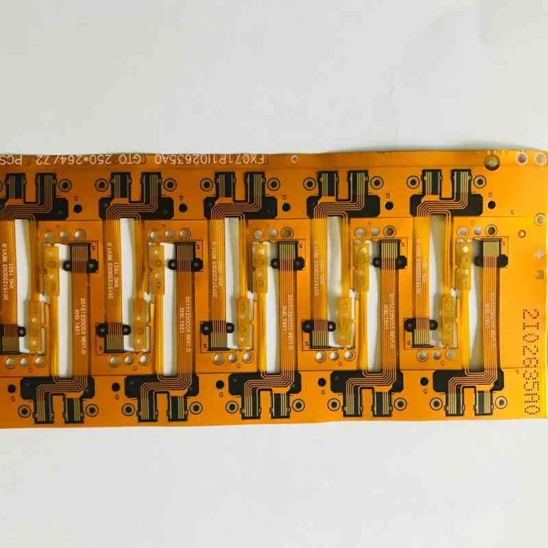
A flexible printed circuit board (FPCB), also known as a flex circuit, is a type of printed circuit board that is made with flexible materials. This allows the board to bend and flex while still maintaining all of its electrical connectivity.
Flexible PCBs consist of flexible dielectric substrates like polyimide or polyester instead of traditional rigid materials like FR-4. The conductive traces are bonded to the substrate using adhesive copper foil.
Benefits of Flexible PCB Boards
Flexible PCB boards offer several advantages over their rigid counterparts:
- Flexibility – Can be bent, folded or twisted to fit mechanically challenging spaces
- Lightweight – Weigh less than rigid boards
- Thin – Extremely thin profile to fit tightly packed electronics
- Durable – Withstand vibration, shock, and flexing cycles
- Customizable – Can be manufactured in variety of shapes and sizes
Some of the key applications that benefit from using an FPCB include:
- Wearable devices
- Medical equipment
- Consumer electronics
- Internet of Things (IoT)
- Automotive electronics
Flexible PCB Construction and Materials
Flexible PCBs have a similar construction to rigid PCBs but use different substrate and trace materials to provide flexibility. Here are the main components:
| Layer | Description |
|---|---|
| Flexible Substrate | Base layer that provides flexibility. Usually made from polyimide or polyester sheets. |
| Adhesive Copper Foil | Copper foil that is laminated to substrate using adhesive. Used to create conductive traces. |
| Coverlay | Protective top layer over circuitry. Polyimide or other flexible dielectric. |
| Stiffener | Optional rigid layer to provide support in certain areas. |
The thickness of each layer can be adjusted to achieve the desired level of flexibility vs. rigidity. Typical thickness ranges from 25 micrometers up to around 200 micrometers.
Popular Flexible Substrate Materials
- Polyimide (PI) – Most common base material. High flex life and heat resistance. Used in Kapton® films.
- Polyester (PET) – Lower cost but less flexible than polyimide. Used in Mylar® films.
- PEN – Polyethylene naphthalate. An alternative to polyimide with better chemical resistance.
- PI Composite – Polyimide films reinforced with glass fiber for extra strength and rigidity.
Flexible PCB Conductor Materials
The conductive traces are typically made from electrodeposited copper foil, rolled annealed copper, or copper alloys. Traces can be plated with gold, tin, or other finishes.
Flexible PCB Design and Layout
Designing the layout for an FPCB requires some special considerations.
Here are some flex PCB layout guidelines:
- Minimize rigid sections to maximize bend radius
- Avoid traces perpendicular to bend line
- Use hatched ground planes instead of solid copper pours
- Place components in neutral bend areas when possible
- Use teardrop pads at junctions between rigid and flex areas
Other tips for optimal flexible PCB design include:
- Account for flex area stretching and shrinkage
- Create gentle flex transitions with rounded corners
- Anchor flexible region edges for strain relief
- Implement measures to reduce EMI
Using flex-capable PCB design software with the right capabilities is recommended for flex and rigid-flex boards.
Flexible PCB Manufacturing Process
Producing flexible PCBs requires some different manufacturing techniques compared to standard rigid boards. However, the overall fabrication process is similar:
1. Circuit Design and Layout
- Create circuit schematic
- Design PCB layout adhering to flex design guidelines
2. Photoimage and Etch Copper Layers
- Print circuit layout onto photosensitive laminate
- Expose boards to UV light through photomask
- Etch away unwanted copper to form traces
3. Laminate Stackup
- Add coverlay, stiffeners, and other layers
- Laminate layers together using adhesive and pressure
4. Component Assembly
- Populate board with components using soldering or conductive adhesive
- Perform visual inspection for defects
5. Testing and Quality Control
- Test board electronics and functions
- Inspect for any damage or lack of performance
- Repeat steps if needed to correct issues
With the right flex PCB manufacturer, high-quality flexible boards can be produced reliably and efficiently.
Flex vs. Rigid Flex PCB Boards
There are two main categories of flexible PCBs:
Flexible PCBs
Consist solely of flexible circuit materials. Can be bent, folded, and flexed continuously. Used when the entire board needs to be dynamic and elastic.
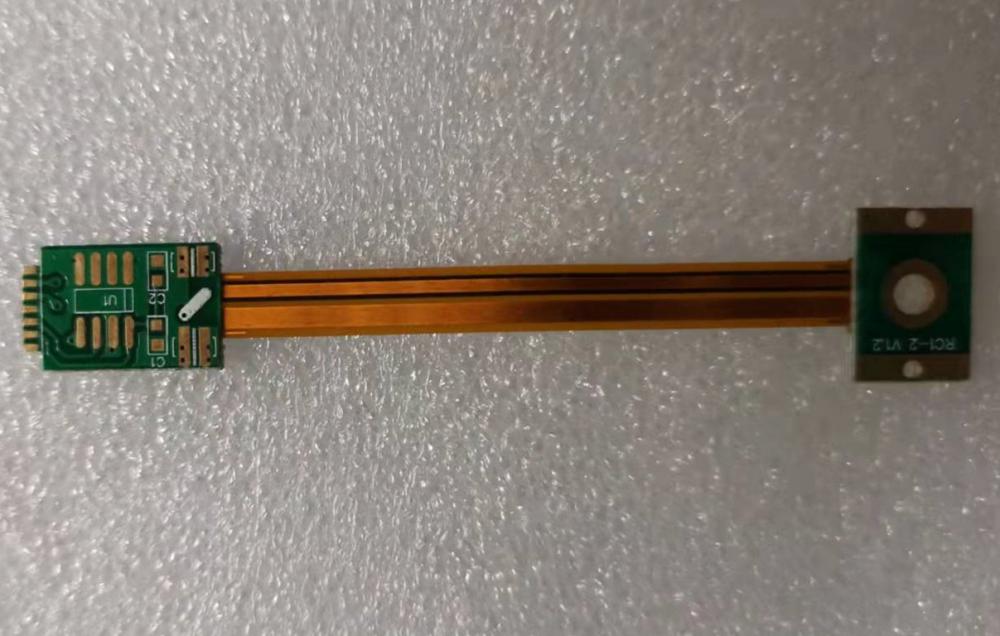
Rigid-Flex PCBs
Contains sections of both flexible and rigid materials laminated together. Allows for more complex 3D assembly while maintaining flexing capability in certain areas.
Rigid-flex PCBs provide the ideal combination of support and flexibility for many applications. They contain both:
- Rigid sections – FR4 or other rigid laminate areas. Provide structure, spacing, and component mounting.
- Flex sections – Polyimide or polyester flexible regions between rigid sections. Enable bending and twisting of the overall board.
Here is a comparison between pure flex PCBs and rigid-flex boards:
| Parameter | Flex PCB | Rigid-Flex PCB |
|---|---|---|
| Composition | 100% flex materials | Combines rigid & flex materials |
| Structure | Entirely flexible | Rigid areas with flexible folds |
| Bendability | Can flex continuously | Flexible in some sections |
| Components | Limited by flex material | Rigid areas allow more mounting |
| Layers | Typically single or double sided | Can have 4-30+ layers |
| Applications | Dynamic, tight spaces | Complex, hybrid designs |
| Cost | Lower | Higher due to more materials |
Flexible PCB vs Rigid PCB Comparison
Flexible PCBs offer some different characteristics from their rigid counterparts:
| Characteristic | Flexible PCB | Rigid PCB |
|---|---|---|
| Composition | Polyimide or polyester base | FR4 glass epoxy base |
| Flexibility | Can be bent and twisted repeatedly | Rigid, no flex capability |
| Thickness | As low as 25 microns | Typically 1.6 mm or thicker |
| Weight | Lightweight | Heavier |
| Layers | Typically 1 or 2 | Up to 30+ layers supported |
| Trace spacing | 5 mil spacing typical | Much finer trace spacing |
| Component mounting | Limited | Components can be surface mounted |
| Automated assembly | Challenging | Easier to use pick and place |
| Production volume | Typically lower quantities | Ideal for mass production |
| Testing | Usually tested before assembly | Can be tested in panels before assembly |
| Cost | Generally higher per area | Lower cost, better economies of scale |
| Durability | Withstands flexing, vibration | Brittle, prone to cracking |
| Applications | Tight spaces, wearables, dynamic bending | Consumer electronics, computers |
As can be seen, rigid PCBs are better suited for high layer counts and dense, inexpensive circuitry. But flexible PCBs provide unique mechanical abilities for challenging form factors.
Common Flexible PCB Applications
Some of the most common uses for FPCBs and flex circuits include:
Wearable Electronics
- Smart watches
- Fitness trackers
- Health monitoring patches
Medical Devices
- Hearing aids
- Wireless sensors
- Implants
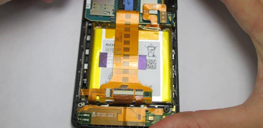
Consumer Electronics
- Mobile phones
- Laptops
- Digital cameras
- E-readers
Automotive
- Backup cameras
- Seat sensors
- Control units
Aerospace
- Avionics systems
- UAVs and drones
Internet of Things
- Networked sensors
- Wearables and devices
The thin, lightweight, and durable nature of flex circuits makes them an ideal choice for many modern electronic products. Their flexibility allows reliable interconnectivity even in the most cramped and contorted spaces.
Advantages and Disadvantages of Flex PCBs
Advantages
- Extremely thin, lightweight, and flexible
- Can conform to 3D shapes
- Vibration and impact resistant
- Handles mechanical strain well
- Good RF transmission characteristics
- Allows high component density
- Improves reliability in dynamic environments
- Enables creative industrial design
- Typically faster and lower cost than wire harnesses
Disadvantages
- Limited in terms of layers and trace density
- Smaller minimum trace width and spacing
- Requires special design considerations
- Can be more expensive than rigid PCBs
- Some challenges with automated assembly
- Repairs can be difficult or impossible
- Requires advanced manufacturing processes
FQA
What are some key design considerations for flexible PCBs?
Some key design considerations for flex PCBs include maintaining proper trace widths and spacing, minimizing 90 degree angles on traces, using hatched copper fills instead of solid copper, accounting for layer stretching and shrinkage, incorporating strain relief features, and adhering to minimum bend radius rules. Smooth curves and flex fold transitions should be used.
What are some typical substrate thicknesses for flexible PCBs?
Typical substrate thicknesses range from around 25 microns on the low end to around 200 microns on the high side. Polyimide films are commonly between 50 to 125 microns. Thinner substrates provide more flexibility while thicker ones offer better rigidity and component mounting.
What are some methods for connecting flex PCBs to rigid PCBs?
Some approaches for connecting flex PCBs to rigid PCBs include using soldered tabs, various connectors like FFV or SMT, pluggable interfaces, hybrid edge card connectors, crimped connections, and anisotropic conductive films. The best approach depends on the specific application.
How many bend cycles can flexible PCBs withstand?
The flex life of polyimide-based flexible PCBs is typically over 100,000 cycles. But the exact life depends on trace design, substrate material and thickness, bend radius, and other factors. Dynamic flex applications require testing to determine the real-world cycle life under the expected bending conditions.
Are rigid-flex PCBs good for more demanding applications?
Yes, rigid-flex PCBs are well-suited for more demanding applications, since they combine the benefits of standard rigid boards with the flexibility of flex circuits. The rigid sections provide structural support for multilayer high density circuits and increased component mounting. The flexible regions enable the dynamic bend radii needed in complex form factors. This makes rigid-flex a good fit for products like mobile devices.


Leave a Reply