Introduction
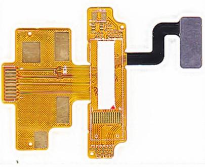
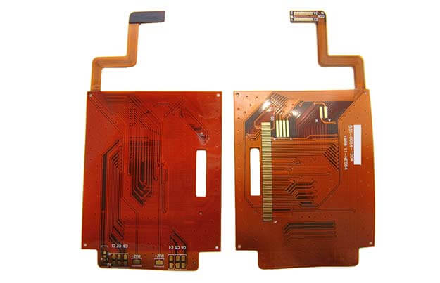
Flex printed circuit boards (flex PCBs) have become increasingly popular in recent years due to their ability to bend and flex to fit into tight spaces. However, this flexibility comes at a cost – without proper support, flex PCBs can be prone to damage during use. This is where flex PCB stiffeners come in. Stiffeners help provide rigidity and prevent flexing in certain areas of the circuit board. In this article, we’ll look at what flex PCB stiffeners are, why they’re important, and provide some best practices for implementation.
What are Flex PCB Stiffeners?
A flex PCB stiffener is a rigid support structure that is attached to a flex circuit board. It serves two key purposes:
- Preventing damage: Stiffeners reinforce the flex PCB and prevent over flexing, wrinkling, or cracking of the copper traces. This ensures the board continues functioning properly under bending and vibration.
- Providing rigidity: Stiffeners give targeted sections of the flex PCB enhanced structure and rigidity. This allows components to be reliably mounted onto the board. It also facilitates handling of the board during manufacturing and assembly.
Stiffeners are typically made from rigid FR-4, polyimide, aluminum, or stainless steel. The material and thickness is selected based on the amount of reinforcement required.
Why are Flex PCB Stiffeners Necessary?

There are a few key reasons why properly designed and located stiffeners are a necessity for most flex PCB applications:
Prevent Trace Damage
The conductive copper traces on a flex PCB are fragile and can crack under repeated bending stress. Stiffeners reinforce the areas around these traces, preventing them from flexing excessively and becoming damaged. This helps ensure reliable functioning of the circuit board.
Reinforce Component Mounting Areas
Surface mount components applied to a flex PCB require a rigid, non-flexing surface for reliable attachment. Stiffeners provide the necessary rigidity and prevent excessive flexing underneath components. This prevents cracking or detachment from the board.
Allow Handling and Assembly
Flex PCBs are delicate and difficult to manage without any rigidity. Stiffeners make handling the boards much easier during assembly and allow use of standard PCB processes and equipment.
Improve Heat Dissipation
The thin polyimide substrate of flex PCBs provides poor thermal conductivity. Stiffeners made from materials like aluminum or steel can act as heat sinks. This channels heat away from hot spots on the board.
Reduce Vibration and Fatigue
Excess vibration can cause material fatigue and connection failures. Stiffeners reinforce areas prone to vibration, helping dampen motion and enhance mechanical life.
Best Practices for Implementing Stiffeners
To maximize effectiveness, flex PCB stiffeners should be designed and implemented appropriately:
- Strategic placement – Only place stiffeners where rigidity is required. Avoid over-stiffening the board as this reduces flex capability in other areas.
- Minimal thickness – Use the minimum thickness required to avoid adding unnecessary weight or inflexibility.
- Allow for thermal expansion – Account for differential thermal expansion to avoid bowing or warping of the assembly.
- Anchor points – Use anchor points to attach the stiffener securely to the PCB for maximum strengthening.
- Limit exposed edges – Masking and sealing the stiffener edges reduces risk of peeling and contamination under the stiffener.
- Divide complex stiffeners – Break up large or complex stiffeners into smaller segments to allow for better flexibility where needed.
- Model and test – Prototype and test the stiffener design to confirm the desired flex performance is achieved.
Common Flex PCB Stiffener Materials

Stiffeners can be fabricated from a range of materials. The most common options include:
| Material | Key Properties |
|---|---|
| FR-4 | Inexpensive, moderate stiffness and temperature resistance |
| Polyimide | High strength and temperature resistance, relatively expensive |
| Aluminum | Excellent stiffness, thermal conductivity, and cost |
| Stainless Steel | High strength and corrosion resistance |
| Plastics | Low cost, limited temperature resistance |
The optimal material depends on mechanical, electrical, thermal, and cost requirements. Both metallic and non-conductive options are available to suit different applications.
Flex PCB Stiffener Design Considerations
Several factors need to be considered when designing stiffeners:
- Stiffness – The stiffener must have adequate rigidity to prevent flexing and reinforce the PCB.
- Strength – It must withstand mechanical stresses without cracking or deforming permanently.
- Size and shape – The size and shape should match the area requiring reinforcement. Minimize overhang.
- Adhesion – Stiffeners should be securely anchored to the PCB with adhesive or mechanical anchoring.
- Thermal expansion – The thermal expansion behavior must be matched to the flex PCB substrate to avoid thermomechanical stresses.
- Outgassing – Outgassing of chemicals from the stiffener material should be minimized to prevent contamination.
- Weight – Adding excessive weight from stiffeners could impact performance in motion-sensitive applications.
- Conductivity – Electrically conductive stiffeners can affect routing and isolation. Insulative materials are often preferred.
- Cost – The cost of both materials and fabrication must be managed, especially in high volume products.
With careful analysis of these parameters, an optimal stiffener design can be achieved.
Potential Issues from Improper Stiffener Use
Failing to utilize stiffeners properly can jeopardize the functionality and reliability of a flex PCB. Some potential issues include:
- Trace cracking – Lack of reinforcement allows traces to fracture under repeated bending stresses.
- Component detachment – Excessive flexing in component mounting areas can lead to cracking or detachment.
- Poor heat dissipation – Insufficient thermal management can lead to localized overheating and damage.
- Broken connections – Unreinforced areas with connectors or heavy components can detach or fracture when flexed.
- Short circuits – Outgassing or inadequate adhesive can cause stiffeners to shift, resulting in short circuits.
- Contamination – Chemical outgassing from poorly sealed stiffeners edges can migrate onto the flex PCB.
- Handling failures – Lack of rigidity can lead to excessive bending, folding, or tearing of the flex circuit during handling and assembly.
Proper stiffener implementation helps avoid these and other potential functional or mechanical failures.
Conclusion
Flex PCB stiffeners provide vital reinforcement to prevent damage while introducing targeted rigidity. When designed and integrated appropriately, stiffeners enable reliable performance of flex circuits under bending and vibration stresses. With careful analysis of mechanical and thermal requirements, optimal stiffener materials and placement can be determined. Following best design practices helps ensure stiffeners enhance durability without over-compromising flex capability.
Frequently Asked Questions
What are the most common places that require stiffeners on flex PCBs?
The most common areas that need reinforcement from stiffeners include:
- High density component mounting locations
- Connectors and cable attachments
- Locations with repetitive bending stress during use
- Sections prone to handling damage during assembly
- Areas with thick copper planes that are susceptible to cracking
How are stiffeners typically attached to the flex PCB?
Common methods of attaching stiffeners include:
- Epoxy adhesive – Provides strong reliable adhesion. Must account for thermal expansion differences.
- Soldering – Can be used for metal stiffeners. Provides electrical connectivity.
- Mechanical anchors – Clips or tabs that grip the PCB edges. Avoid points of high stress concentration.
- Lamination – Stiffeners can be embedded in the PCB laminate for very robust attachment.
Should stiffeners cover the entire area or just targeted sections?
In most cases, stiffeners should only reinforce the specific areas that require rigidity, rather than covering a wide area. This focused targeting preserves flexibility in other areas. However, in cases such as providing an overall rigid frame for handling, a larger stiffener may be warranted.
How thick should typical stiffeners be?
Stiffener thickness depends on the material used and degree of reinforcement needed. As a general guideline:
- Plastic: 0.3mm to 1mm
- FR-4: 0.8mm to 1.6mm
- Aluminum: 0.8mm to 2mm
- Steel: 0.2mm to 0.5mm
Thicker stiffeners provide more rigidity but add weight and cost. Use the minimum thickness that provides adequate support.
Can stiffeners affect circuit performance or routing?
Electrically conductive stiffeners can potentially impact circuit routing, isolation, impedance, and RF performance. Insulating materials like plastics or polyimides are generally recommended to avoid electrical effects. Prototyping and testing should validate the stiffener’s impact on performance.


Leave a Reply