Introduction
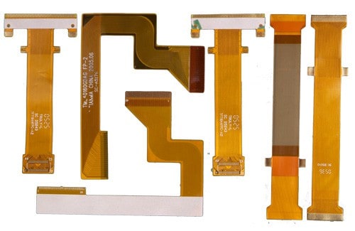
Flex circuits, also known as flexible printed circuits (FPCs), have become ubiquitous in modern electronic devices. As gadgets become smaller and more portable, flex circuits allow manufacturers to fit electronics into tight spaces. However, the flexibility of these circuits comes at a cost – they can be prone to bending, twisting, and vibration. This is where flex circuit stiffeners come in.
Stiffeners add rigidity to flex circuits, preventing damage and maintaining performance. In this article, we’ll explore what flex circuit stiffeners are, why they’re needed, and the different types available. We’ll also discuss optimal stiffener placement and other design considerations for stable and reliable flex circuits. Whether you’re an electrical engineer, PCB designer, or manufacturer, understanding stiffeners is key to flex circuit success.
What Are Flex Circuit Stiffeners?

A flex circuit stiffener is a rigid material layer attached to a flex circuit to add strength and stability. Without a stiffener, a thin, flexible circuit would be too flimsy for practical use in electronics and could easily deform during manufacturing or operation. Stiffeners prevent unwanted bending and vibration that could degrade performance or cause complete failure.
Stiffeners are typically made from rigid plastic or metal. Common plastics used include polyimide (PI), polyethylene terephthalate (PET), polycarbonate (PC), and others. Aluminum is a popular metal option. The stiffener thickness is tailored to the application, but typically ranges from .002” to .010”. Stiffeners can be attached to one or both sides of the flex circuit.
Why Are Stiffeners Needed?
There are several key reasons stiffeners are indispensible for flex circuits:
1. Prevent Short Circuits
Unwanted bending and flexing of a circuit can cause conductors to touch, leading to short circuits and device failure. The rigid surface provided by a stiffener keeps the flex circuit safely in its intended position.
2. Maintain Mechanical Stability
The thin flexible material used in flex circuits provides almost no mechanical support. Stiffeners prevent deformation such as warping and twisting which could damage circuits or connections to other components.
3. Allow SMT Attachment
Surface mount soldering is often needed to attach components to a flex circuit. Stiffeners prevent circuits from flexing during reflow soldering processes.
4. Manage Thermal Stresses
Different coefficients of thermal expansion between conductors, dielectric films, and components induce stresses during thermal cycling. Stiffeners provide rigidity to minimize these stresses on delicate circuits.
5. Prevent Cable Bend Failures
Flex circuits are often used as flexible cable connections between rigid PCBs or components. A stiffener provides the tear resistance and bend radius control needed for reliable performance.
Types of Flex Circuit Stiffeners
There are three primary categories of flex circuit stiffeners:
Integral Stiffeners
Integral stiffeners are built into the flex circuit itself, by using thick dielectric layers or additional laminated layers of rigid plastic:
- Rigid polymeric layers – Additional layers of thick plastic, such as 0.005” polyimide or polyester layers. Simple and cost effective but increase total thickness.
- Cover layers – Same as above, but coverlay (adhesive & polymer layers) laminated over flex circuitry for protection. Adds thickness.
- Copper stiffeners – Thick copper layers, etched to desired pattern, laminated within flex circuit. Adds minimal thickness.
Separate Stiffeners
Discrete stiffener components attached to flex circuit:
- Plastic stiffeners – Sheets of polyimide, PET, PC glued or laminated to flex circuit. Low cost but limited thickness.
- Metal stiffeners – Aluminum, steel, or copper plates for maximum rigidity. Heavier but very effective. Adhesive, solder, or mechanical fastening.
Combo Stiffeners
Pairing integral and separate stiffener technologies
- Plastic + metal – Metal stiffener with plastic insulator attached to flex circuit. Very rigid and protected.
- Copper + plastic – Integral copper stiffener traces combined with plastic overlay. Balances thickness and rigidity.
| Type | Pros | Cons |
|---|---|---|
| Integral Polymer | Simple, thin | Limited rigidity |
| Integral Copper | Thin, rigid | Complex fabrication |
| Separate Plastic | Low cost | Thickness limits |
| Separate Metal | Very rigid | Heavy, expensive |
| Combo | Balances rigidity, protection, and cost | Moderate complexity |
Optimal Stiffener Design and Placement
To achieve maximum benefit from stiffeners, they must be designed and positioned appropriately:
- Place stiffeners along areas of highest stress – near connectors, points of flexing, and high density circuitry
- Extend stiffeners slightly beyond components to prevent local bending
- For cables, use spine stiffeners running along length and anchor points
- Allow small gaps between stiffener sections to relieve thermal stresses
- Align stiffener placement with support structures or frames in assembly
- Use generous fillets at edges to eliminate sharp corners producing stress concentrations
- Include cutouts or holes for mounting hardware or access to assembly features
- Ensure sufficient adhesion strength through mechanical or chemical bonding
- Avoid overlapping stiffener sections, thermal expansion will induce buckling
Proper stiffener design takes into account application stresses, circuit layouts, industrial design, assembly methods, thermal management, and more. FEA and prototyping are recommended to refine the optimal solution.
Other Flex Circuit Design Considerations
While stiffeners improve the stability and rigidity of flex circuits, other design factors also contribute to reliability:
- Conductor width and spacing – Wide traces with adequate spacing help prevent shorts
- Dielectric material – Polyimide films provide excellent thermal and mechanical properties
- Number of conductive layers – 4-8 layers are common, limiting flexibility
- Conductor thickness – 1-2 oz (35-70 μm) copper foils are typical, thicker resists damage
- Flexible substrate thickness – Standard 1-3 mil flex materials, up to about 8 mils
- Bend radius control – Limit sharp folds, allow sufficient bend radius
With careful engineering and testing, stiffeners and robust flex circuit design enables reliable functioning in even the most demanding applications.
Frequently Asked Questions
Q: How thick are flex circuit stiffeners?
Typical stiffener thickness ranges from .002” to .010”. Rigid polymers and thin metal foils provide adequate reinforcement without excess bulk.
Q: Can you solder components to flex circuits with stiffeners?
Yes, standard reflow and wave soldering processes work well. Stiffeners prevent warping and damage during soldering. SMT, thru-hole, and mixed technology are supported.
Q: Are stiffeners required for all flex circuits?
While not strictly required, most robust flex circuits benefit from stiffening. Simple cables with mild stresses may not need them. Stiffeners become more important as density and complexity increases.
Q: Can stiffeners be added after flex circuit fabrication?
Yes, separate plastic or metal stiffeners can be attached in a secondary process using adhesive, solder, or mechanical fasteners. But integral stiffeners lend themselves to easier assembly.
Q: How do I know if I need more or less stiffening?
Physical testing of prototypes under realistic mechanical and thermal conditions is the best way to calibrate required stiffening. FEA simulation can also provide guidance during design.
Conclusion
Flex circuit stiffeners are a simple but critical component enabling stable, reliable performance of flexible printed circuits. The optimal stiffener design depends on careful consideration of circuit topology, assembly methods, application stresses, and other factors. With robust engineering, stiffeners allow flex circuits to survive and thrive in the challenging conditions found across industrial, consumer, automotive, aerospace, and medical products. As flexible circuits continue proliferating, thorough understanding of stiffener best practices will be essential knowledge for digital designers and engineers across disciplines.


Leave a Reply