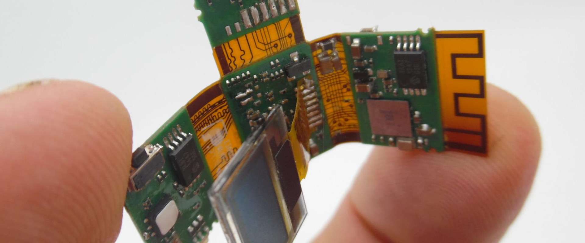
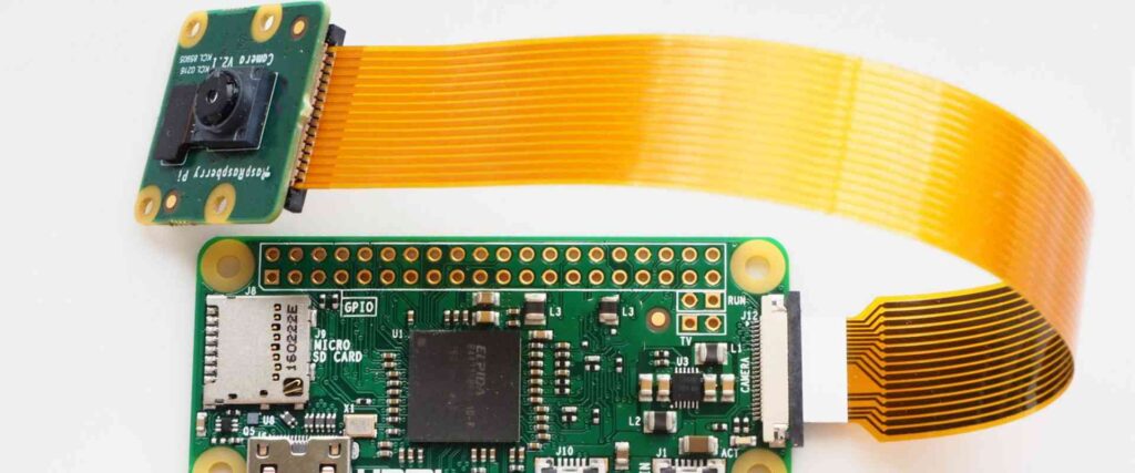
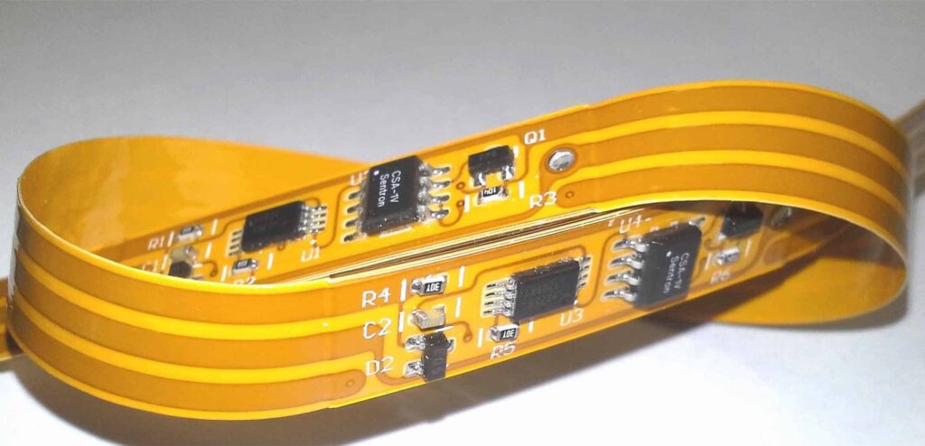
Flexible printed circuits (FPCs), also known as flex circuits, are a type of printable circuitry made using flexible insulating substrate materials such as polyimide film. Compared to traditional rigid printed circuit boards (PCBs), flex circuits can bend and flex to fit into tight or movable spaces in electronic devices. Flex circuits allow for more compact and lightweight circuit designs while still maintaining reliability and performance. This makes them ideal for many modern consumer electronics, medical devices, aerospace applications, and more. However, specialized design and manufacturing processes are required to work with flex circuits versus standard rigid boards. This article provides an in-depth guide on flex circuit assembly, covering key design considerations, manufacturing steps, assembly methods, common defects to avoid, and frequently asked questions.
Design Factors for Flex Circuits
Several unique factors need to be considered when designing a flex circuit versus a traditional rigid PCB:
Substrate Materials
The most common flexible substrate materials are polyimide films like Kapton or Upilex. Thickness typically ranges from 1-3 mils (25-75 μm). Thinner substrates allow for tighter bend radii while thicker films offer better dimensional stability and ease of handling. Other options like polyester (PET) or PEEK films are also used in some cases.
Conductor Materials
Copper is most commonly used due to its high conductivity and flexibility. Rolled annealed copper foils around 1-2 oz (35-70 μm) are typically laminated to the polyimide base film. Electroplated copper may be used in some instances. Other conductor materials like aluminum or silver inks are also possible for specialty applications.
Layer Stackup
Single, double, and multilayer flex circuits can be fabricated. Complexity increases with more layers, but allows for higher circuit density and more routing options. Common layer counts are 1-6 layers.
Bend Radius
The minimum bend radius the flex circuit can tolerate must be defined based on substrate/conductor thicknesses and materials used. Tighter radii allow for more compactness but require thinner/more flexible materials.
Stiffener Materials
Sections of a flex circuit may need stiffener materials like FR4 or polyimide film layers added for mounting components, connectors, etc. Stiffened areas obviously cannot bend.
Registration
Precise alignment of circuit features/vias across layers is critical, especially for high density designs. Tight registration tolerances are required.
Flex Circuit Fabrication Process
Fabricating a flex circuit involves specialized processes and equipment versus standard PCB fabrication. Here are the key manufacturing steps:
Substrate Preparation
The flexible base substrate film is cleaned, then treated with processes like corona treatment or chemical etches to improve adhesion.
Conductor Lamination
Copper foil is laminated to the substrate using heat and adhesive. Rolled annealed copper around 1-2 oz is most common.
Imaging
A photoresist is coated onto the copper layers and then selectively exposed/imaged using lithography processes.
Etching
The exposed copper is etched away, leaving behind the desired circuit pattern protected by photoresist.
Photoresist Stripping
The remaining photoresist is then removed, revealing the final circuit traces and features.
Solder Mask Application
A solder mask coating is applied and cured to insulate the exposed traces and prevent solder bridges.
Finishing
Finished parts may go through additional steps like via formation, plating, stencil printing, etc. depending on design.
Soldering
Solder pads, component leads, or connectors are soldered using reflow or selective soldering methods.
Testing
Each circuit is electrically tested against short/open failures before shipment.
Flex Circuit Assembly Methods
There are several approaches to assembling components onto flex circuits:
SMT Assembly
Surface mount components can be directly mounted onto flex circuits using standard SMT assembly processes with solder paste and reflow. Modifications may be needed to allow for some flexing.
Plated Through Holes
Leaded components can be soldered to plated through holes in the flex circuit via wave or selective soldering. Holes need to be properly reinforced.
Connectors
Mated connectors can be soldered to mounting pads on the flex circuit for integration with other circuitry.
Adhesives
Some components may be attached using conductive or non-conductive adhesives rather than solder. Allows for rework and minimizing solder.
Hybrid Assembly
Combinations of the above approaches may be used. Some sections may use SMT, others plated through holes, etc.
Stiffener Integration
Any required stiffeners are laminated or adhered to the flex circuit prior to component assembly.
Common Defects to Avoid
Special care must be taken to avoid these potential error modes in flex circuit assembly:
- Lost adhesion between layers due to insufficient surface prep or lamination pressure.
- Registration errors between layers leading to misaligned vias or features.
- Overetching resulting in thin/discontinuous circuit traces.
- Solder voids or bridges from ineffective soldering or excess solder paste.
- Cracks in traces or pads due to bending beyond minimum radius.
- Delamination between flexible substrate and stiffeners.
- Tenting of plated through holes from excess solder mask.
- Outgassing from the substrate during lamination or other processes.
Careful process controls and inspection steps are key to minimizing defects and rework.
Flex Circuit Assembly FAQ
Here are some frequently asked questions about flex circuit assembly:
What are the main benefits of using flex circuits vs. rigid PCBs?
Flex circuits allow for compact, dynamic, and lightweight circuit designs by bending to fit product enclosures. They can improve reliability by reducing mechanical stresses. They enable applications involving motion or articulation.
What types of products commonly use flex circuits?
Consumer electronics, medical devices, automotive, aerospace, and industrial equipment are major users of flex circuitry. Any application where a rigid board would be inconvenient or unreliable is a candidate.
Are there limitations on component size or density with flex circuits?
The flexible substrate does impose some limits versus rigid boards. But modern processes allow fairly high density SMT parts, smallvias, etc. Generally multiple thin flex layers are used rather than one thick rigid layer.
Can existing PCB assembly processes be used for flex circuits?
Some modifications are usually needed to account for the flexing material properties. Handling, clamping, and soldering processes need to adapt to avoid damaging traces or pads.
How should flex circuits be handled and stored to prevent damage?
Avoid sharp bending beyond the minimum bend radius. Store in shipping frames with support at bends to avoid taking a permanent set over time. Keep clean and protected from environmental exposure.
How are components prototyped and tested on flex circuits before full production?
Short prototype runs with nonfunctional “coupons” are often tested to verify assembly processes before full production. Rigid-flex boards with integrated testpoints can also be used.
In summary, flex circuits require specialized design and manufacturing processes, but offer unique advantages of compactness, dynamic bending, and improved reliability compared to standard rigid PCBs. By following robust assembly methods and avoiding common defects, quality and yields can meet the demands of modern flex circuit applications.


Leave a Reply