Introduction
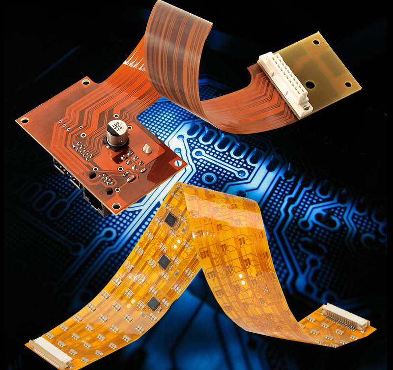
A flexible printed circuit board (flex PCB or flex circuit) is a type of printed circuit board made of flexible materials like polyimide. Flex PCBs can be bent, folded, twisted and shaped to fit into tight spaces and movable parts. They are ideal for products that require flexibility, like medical devices, wearables, robotics, and consumer electronics.
While flex PCBs provide many advantages like flexibility, weight savings, and space savings, they also come with some unique disadvantages compared to rigid PCBs. In this article, we will examine the key disadvantages of using flex PCBs.
Disadvantages of Flex PCBs
More expensive
One of the main disadvantages of flex PCBs is their higher cost compared to rigid PCBs. Here are some of the reasons why flex PCBs tend to be more expensive:
- Raw materials – The base material for flex PCBs like polyimide and adhesive layers is more expensive than standard rigid PCB materials like FR-4.
- More complex manufacturing – Producing flex PCBs requires more manual processing and specialized equipment suited for flexible materials. This increases production costs.
- Lower economies of scale – As flex PCB production volumes are lower compared to rigid PCBs, manufacturers cannot benefit as much from economies of scale to reduce costs.
- Testing – The flexible nature of flex PCBs requires more rigorous stress testing to validate performance under bending and flexing conditions. This adds to costs.
In general, flex PCBs tend to cost at least 2-3 times more than equivalent rigid PCB designs. The cost premium must be weighed against the space, weight and flexibility benefits.
Challenging design and assembly
Designing and assembling flex PCBs comes with some unique considerations, especially when combining rigid and flex portions into one design:
- Routing – Traces on flex PCBs need to be routed keeping in mind dynamic flexing conditions to avoid failures. This may limit routing options.
- Stiffeners – Rigid sections or stiffeners may be required to prevent unwanted bending in certain areas. These add complexity.
- Component mounting – Components on flex PCBs are subjected to more mechanical stresses. Their mounting and attachment need careful design.
- Folding – Folded or rolled sections need appropriate minimum bend radii to avoid damage. Sharp folds should be avoided.
- Testing – More testing is required to validate the design under bend cycles and various use conditions.
The specialized design rules and constraints can make flex PCB design more complex and challenging compared to rigid PCBs.
Limited capabilities
Flex PCBs come with some inherent limitations in terms of capabilities:
- Number of layers – Flex PCBs are typically limited to 2 or 4 layers while rigid boards can have 8 layers or more. This constrains routing capabilities for complex designs.
- Line width/spacing – The minimum trace width and spacing is larger on flex PCBs – around 100 micron compared to 50 micron or lower on rigid boards. This also limits routing capabilities.
- Hole size – Minimum hole size on flex PCBs is around 400 micron versus 150 micron on rigid boards. Larger vias take up more space.
- High frequency/speed – The transmission line capabilities of flex PCBs are inferior to rigid boards, especially for signals above 1 GHz. This restricts their use in high frequency applications.
The limited capabilities may prevent flex PCBs from meeting requirements of some complex, high density or high speed designs.
Reliability concerns
The dynamic flexing nature of flex PCBs can raise some reliability concerns:
- Flex cracks – Repeated bending and flexing can cause cracking of the conductor traces over time leading to electrical failure.
- Interconnect failure – Failures can occur in components mounted across flex/rigid interfaces due to mechanical stresses.
- Via reliability – Plated through hole (PTH) reliability is generally lower compared to rigid boards under dynamic conditions.
- Degradation – Flex PCB materials can degrade over time with exposure to environmental conditions and become brittle.
While thorough testing helps validate reliability, it generally lags behind the field data available for mature rigid PCB technology. Design margins and guard banding are essential.
Limited supplier base
As flex PCBs represent a small portion of the total PCB market, the number of qualified vendors is fewer compared to the vast supplier base for rigid PCBs. This can constrain procurement options, lead times and competition.
However, the market is expanding steadily with more suppliers adding flex PCB capabilities. This situation is improving gradually.
Key Applications Despite Disadvantages
Despite the disadvantages, flex PCBs offer indispensable benefits for many applications:
- Wearable devices
- Medical electronics
- Mobile phone flex cables
- Automotive camera modules
- Robotics joints
- Aerospace assemblies
- Consumer electronics
In these cases, the disadvantages are mitigated by proper design, testing and qualification. As flex PCB technology matures further, capabilities are also improving.
Summary
Here are some of the key disadvantages and considerations when using flex PCBs:
- Higher cost vs rigid PCBs
- More complex and challenging design
- Limitations in routing, layer count, density etc.
- Potential reliability concerns under dynamic bending
- Fewer qualified supplier choices
However, the disadvantages are usually outweighed by the substantial space, weight, and flexibility benefits of flex PCBs in many applications. With careful design and testing, flex PCBs provide a versatile interconnect solution not achievable with rigid technology alone. As the market expands, flex PCB capabilities and cost effectiveness will continue to improve.
Frequently Asked Questions (FAQ)
Q1. Can flex PCBs match the circuit density of rigid PCBs?
No, flex PCBs generally have lower circuit densities compared to rigid PCBs. They are limited to 2-4 layers while rigid boards can have far greater layer counts. The minimum trace width and spacing is also higher on flex PCBs. These factors restrict the achievable circuit density.
Q2. Are flex PCBs suitable for high frequency applications?
Flex PCBs tend to have poorer high frequency performance compared to rigid boards. Above 1 GHz, the transmission line capabilities degrade significantly. They also cannot provide proper impedance control at high frequencies. So they are not suitable for most very high frequency applications.
Q3. How thick are typical flex PCBs?
Flex PCB thickness typically ranges from about 25 microns (1 mil) to around 150 microns (6 mils). Rigid portions can be thicker. Thinner flex PCBs provide maximum flexibility while thicker ones are more rugged.
Q4. Can surface mount components be used on flex PCBs?
Yes, flex PCBs support a variety of surface mount components like resistors, capacitors, ICs etc. However, their attachment and mounting requires more attention compared to mounting on rigid PCBs due to the potential for mechanical stresses.
Q5. How long do flex PCBs last?
Under normal environmental conditions and flexing cycles, flex PCB life expectancy is typically over 50,000 cycles. With proper design, robust components and protection, several million flex cycles can be achieved. Thorough testing helps validate expected lifetimes.


Leave a Reply