Introduction to Flex PCBs
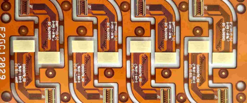
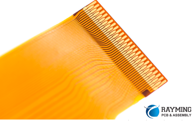
A flex PCB (flexible printed circuit board) is a type of PCB that can bend and flex. Flex PCBs are made from flexible materials like polyimide instead of rigid materials like FR4. They have applications where flexibility, space savings, or durability are required.
Flex PCBs have been around since the 1950s but have become more popular in recent years due to advances in manufacturing and component technology. Their key benefits include:
- Flexibility – can conform to different shapes and spaces
- Durability – resistant to vibration and impulse shocks
- Space savings – takes up less space than rigid PCBs
- Weight savings – lighter than rigid PCBs
- High frequency – low signal loss at high frequencies
Common applications of flex PCBs:
- Consumer electronics – cell phones, wearables, VR headsets
- Automotive – sensors, engine controls, LED lighting
- Medical – imaging equipment, implants
- Industrial – robotics, aviation and aerospace
Types of Flex PCBs
There are several types of flex PCBs, classified by their structure:
- Single-layer – one conductive layer
- Double-layer – two conductive layers
- Multilayer – more than two conductive layers
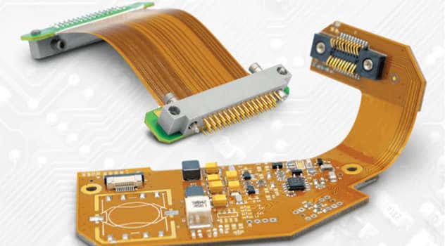
- Rigid-flex – combination of rigid and flex PCBs
- Flexible rigid – flex PCB with stiffeners
The number of layers and type used depends on the design requirements like complexity, space, and cost.
Benefits of Custom Flex PCBs

For many applications, using an off-the-shelf or generic flex PCB may not meet the exact design, size, or functionality required. This is where a custom-designed flex PCB offers key advantages:
Optimized Size and Shape
A custom flex PCB can be designed to precisely fit the target space and shape requirements. This optimization saves space and weight compared to having to use a larger off-the-shelf PCB.
Component Placement
With a custom design, components can be optimally placed to maximize performance and reliability. Signal paths can be laid out for minimal length and noise.
Complex Circuits
A custom flex PCB supports more complex circuit designs with more layers and components than generic boards. Complex flex-rigid PCB combinations are also possible.
Cost Savings
Although custom PCBs have higher initial design costs, they can significantly reduce manufacturing costs at scale compared to using multiple generic PCBs.
Performance
Careful layout and routing of custom flex PCBs minimize parasitic losses, enabling higher frequency, higher speed signals.
Reliability
A custom flex PCB tailored for the application environment will outperform a generic board over the product lifetime.
Product Differentiation
A custom flex PCB design provides a unique solution that competitors using off-the-shelf boards won’t have.
For critical applications where size, performance, cost, and reliability matter, a custom designed flex PCB is worth the investment.
The Custom Flex PCB Design Process

Designing a custom flex PCB requires careful planning, engineering analysis, layout, prototyping, and testing. Here are the key stages:
Requirements Gathering
The design goals, space constraints, performance targets, and environmental conditions are defined. Required components, materials, and interfaces are determined.
Conceptual Design
Potential layouts and routing plans are drafted to meet the requirements. Engineering tradeoffs are analyzed to refine the design.
Detailed Design
Board layers, dimensions, copper weights, and mechanical properties are specified. Components are footprinted and precisely placed. Signal and power nets are routed.
Prototyping
Prototypes are fabricated and assembled for initial validation. Design flaws are identified and corrected in an iterative process.
Compliance Testing
The finished design undergoes applicable regulatory testing for quality, safety, and standards conformance. Issues found require design modifications.
Manufacturing
Once the design is finalized, fabrication and assembly tools are setup for volume production. Quality processes are implemented to catch defects.
Choosing a Flex PCB Manufacturer
Choosing the right flex PCB manufacturing partner is critical for delivering a successful custom product. Here are key selection criteria:
- Experience – Number of years building flex PCBs, especially in your industry. Look for experience with complex multi-layer and flex-rigid designs.
- Technical Capabilities – Assess their design expertise, manufacturing capabilities, available assembly services, and quality processes. Ensure they can manufacture your design.
- Quality – Look for certifications like ISO 9001 and positive customer reviews. Evaluate process capabilities and inspection rates.
- Prototyping Services – The ability to iteratively prototype and test boards during development is invaluable.
- NPI Services – Assistance with design reviews, DFM, compliance testing, and transitioning to production.
- Customer Service – Responsiveness to requests and issues. Clarity of communications.
- Cost – Budgetary quotes for small and volume orders. Expected costs for design services, tooling, and NPI.
- Location – Factor geographic proximity, time zones, shipping costs, and lead times.
| Criteria | Weight | Vendor 1 | Vendor 2 | Vendor 3 |
|---|---|---|---|---|
| Experience | High | 8/10 | 7/10 | 6/10 |
| Capabilities | High | 9/10 | 7/10 | 8/10 |
| Quality | High | 8/10 | 9/10 | 7/10 |
| Prototyping | Medium | 10/10 | 6/10 | 8/10 |
| Services | Medium | 7/10 | 8/10 | 9/10 |
| Customer Service | Low | 8/10 | 9/10 | 7/10 |
| Cost | Medium | 7/10 | 8/10 | 9/10 |
| Location | Low | 9/10 | 6/10 | 7/10 |
| Total Score | – | 8.4 | 7.6 | 7.7 |
Flex PCB Design Guidelines
To ensure a successful custom flex PCB project, here are some key design guidelines:
- Minimize flexing – Avoid sharp folds and bends. Design strain relief into the flex layer.
- Avoid brittle materials – Use polyimide instead of FR4 layers which can crack under bending.
- Pad adhesive wells – Adhesive keeps components attached under dynamic flexing.
- Anchor rigid sections – Use diverse attachment points on rigid sections to avoid detachment.
- Shield RF sections – Prevent RF leakage and interference by shielding high frequency traces.
- Reinforce connection points – Avoid separation of connectors and tabs under flexing with additional adhesive or anchoring.
- Test flex durability – Validate the design by rapid flex cycle testing of prototypes.
Following established flex PCB design rules and working closely with your manufacturing partner will ensure your product meets all mechanical and electrical requirements.
Cost Factors for Custom Flex PCBs
Here are some of the main factors that determine the cost of a custom flex PCB:
- Board Size – The dimensions of the flex PCB impact raw materials cost.
- Layer Count – Each conductive copper layer adds significant cost due to additional processing steps.
- Flex vs Rigid Layers – Flexible layers typically cost more than standard FR4 rigid layers.
- Material Type – Specialty materials like polyimide or high-frequency dielectrics have higher costs than standard FR4 material.
- Board Thickness – Thicker boards require more materials and processing time.
- Laminations – Multiple laminations add labor and material expenses. Foil lamination is more costly than silkscreen.
- Fine Line Trace/Space – Tighter trace spacing and thinner traces require advanced fabrication capability.
- Finish Type – Special finishes like gold plating are more expensive than standard HASL, OSP or immersion finishes.
- Tolerances – Tighter tolerances demand additional setup and inspection time to achieve.
- Testing/Certifications – Any additional testing like IST or certifications add labor hours.
- Lead Time – Rush orders with tighter deadlines have higher associated costs.
- Order Volume – One-off prototype costs are higher than volume production pricing.
FQA
What is the typical lead time for a custom flex PCB?
For prototyping small batches, the lead time is typically 5-10 business days. For volume production orders, depending on complexity, lead times range from 2 to 4 weeks.
What design software is used for flex PCBs?
Flex PCB design requires specialized CAD tools like Altium Designer, Cadence Allegro, or Mentor Xpedition. These tools support complex flex capabilities.
How durable are flex PCBs?
Properly designed flex PCBs can endure millions of dynamic flex cycles. Rigorous prototype testing verifies the mechanical durability. Polyimide material resists cracking far better than FR4.
How small can flex PCB traces and spaces be?
Using advanced fabrication techniques like laser etching, trace and space can reach 2 mils or lower. Typical values range from 4 to 6 mils.
Can flex PCBs have components on both sides?
Yes, double-sided component mounting is supported, but requires adhesives and anchoring attachments to withstand dynamic flexing.


Leave a Reply