Introduction to Coverlay PCBs
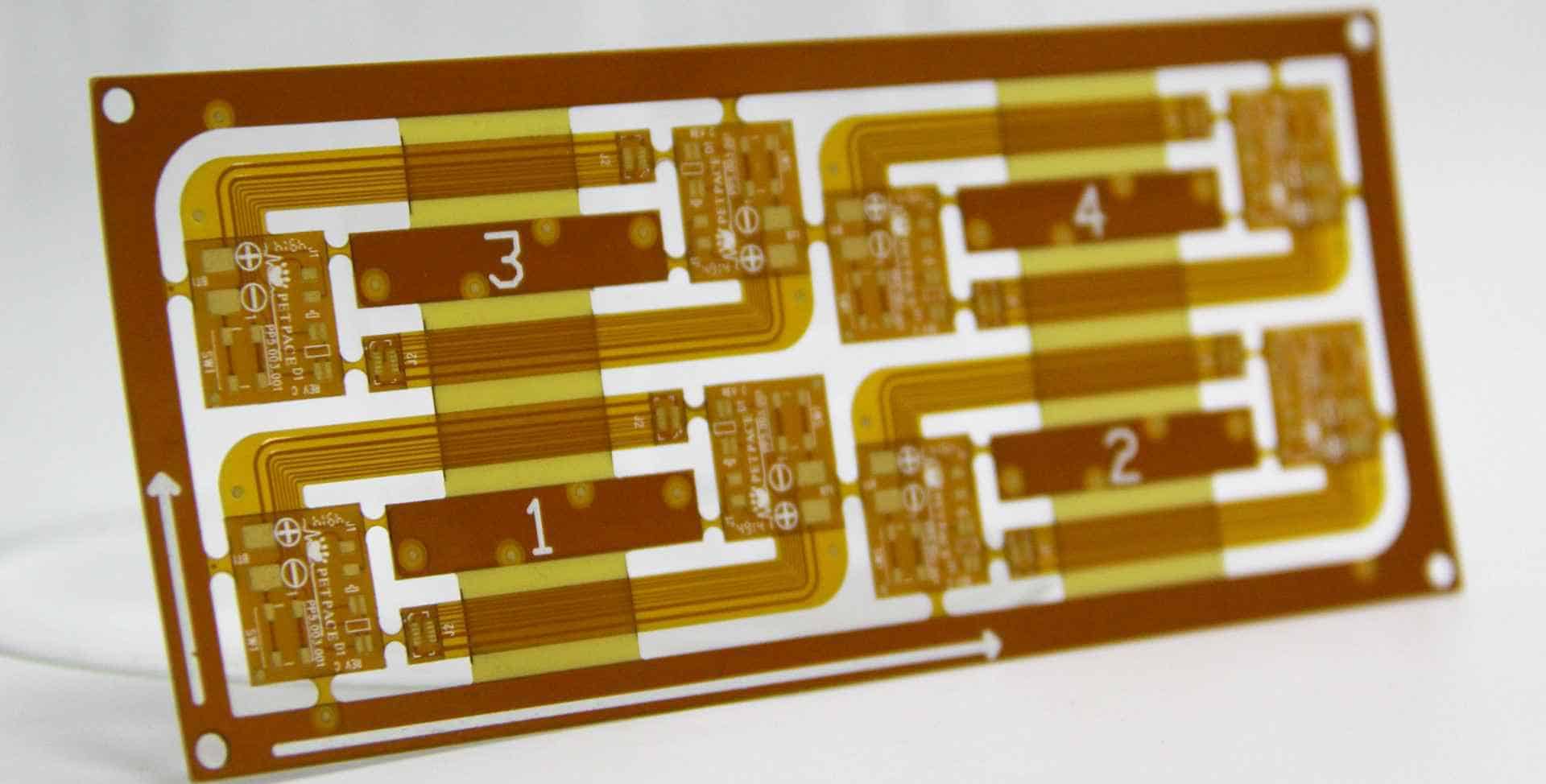
A coverlay PCB (also known as a cover film PCB) refers to a printed circuit board (PCB) that utilizes a thin, flexible insulating material called a coverlay to coat and protect the traces and components on the board. The coverlay film is laminated onto the PCB substrate, covering everything except the solder pads and vias. This provides a layer of insulation and protection from the environment, helping prevent shorts, corrosion, arcing and other damage to the PCB.
Coverlay PCB technology offers a number of benefits:
- Reliable protection – The coverlay material seals vulnerable traces and components from exposure to moisture, debris, chemicals and other contaminants. This enhances the durability and lifespan of the PCB.
- Insulation – Coverlay films have excellent dielectric properties to prevent short circuits between traces and electrical components on densely populated PCBs.
- Weight savings – Using coverlay allows PCBs to be designed with thinner base materials, reducing overall weight.
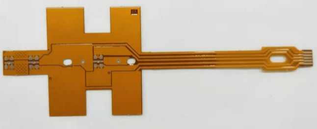
- Flexibility – Many coverlay films are designed to be ultra-thin yet flexible, allowing them to coat flex PCBs and other dynamic or bendable circuit boards.
- Repairability – Damaged coverlay can be repaired or replaced, unlike conformal coatings which are permanent coatings on a PCB.
Coverlay PCBs are commonly found in aerospace, defense, telecommunications, medical, industrial and automotive electronics where reliability, flexibility and repairability are critical factors.
Coverlay Film Materials and Properties
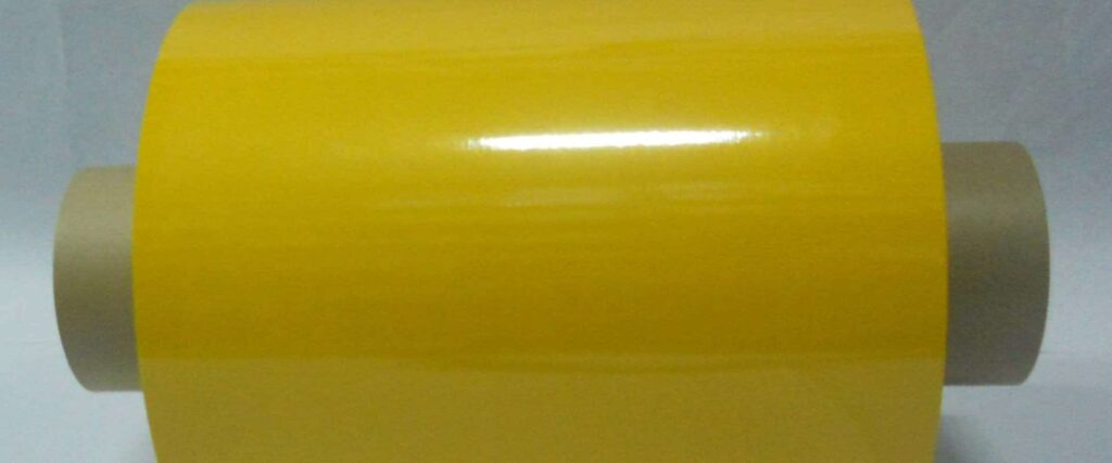
Several material types are used to manufacture coverlay films, with polyimide being the most common. Some key properties to consider when selecting a coverlay material include:
- Dielectric strength – This determines how effectively the material can insulate between conductors at various voltages. Materials with high dielectric strength are less prone to electrical arcing or dielectric breakdown.
- Thermal stability – Ability to maintain mechanical and electrical properties under elevated temperatures without deformation or degradation. This is especially important for PCBs used in high temperature environments.
- Chemical resistance – Resistance to solvents, fluids and other chemicals that may contact the PCB surface.
- Flexibility – Ability to conform to flexible and dynamic PCB substrates without damage, cracking or excessive stiffening.
- Adhesion – Bond strength between coverlay and PCB substrate. Coverlay should remain secured to board under thermal cycling, vibration, flexing and other stresses.
- Flammability – Materials with higher flammability require flame retardant additives to meet safety standards in many electronics applications.
- Thickness – Typical coverlay films range from 12.5 to 100 microns thick. Thinner films maximize flexibility and produce minimal change to board thickness.
Some common coverlay materials used in PCB fabrication:
| Material | Key Characteristics |
|---|---|
| Polyimide | Excellent thermal stability and chemical resistance. Most common coverlay type. |
| Polyester/PET | Low cost but limited thermal resistance. |
| Polyurethane | Good flexibility. Low flammability. |
| Epoxy | Harder and less flexible than other options. |
| Parylene | Provides ultra-thin pinhole free coating. |
Coverlay Application and Processing
There are several steps involved in integrating coverlay protection into the PCB manufacturing process:
Surface Preparation
The PCB substrate surface must be thoroughly cleaned to maximize coverlay adhesion. Any contaminants, oxidation or films left on the board surface can compromise bonding. Both chemical and mechanical cleaning techniques are commonly employed.
Coverlay Cutting
The coverlay material is cut into sheets to match the dimensions of the PCB substrate. Precise cutting is needed to ensure the coverlay fully seals the board while leaving solder pads uncovered. Automated cutting tools are programmed to match the PCB design.
Coverlay Lamination
The coverlay sheet is carefully aligned over the PCB and then laminated onto the board using a combination of heat and pressure. Typical lamination temperatures range from 175°C to 200°C. The elevated temperatures soften the coverlay material allowing it to flow and conform closely to the PCB surface topography.
Via Opening
Once laminated, the coverlay must have vias precisely formed through it to uncover solder pads. Mechanical milling and drilling are typically used, along with laser cutting and plasma etching on thinner coverlays. The via openings alignment is critical for quality.
Curing/Annealing
A final curing step hardens the coverlay material and improves adhesion strength through crosslinking. Curing is done in an oven or autoclave at temperatures exceeding the initial lamination temp.
Testing
100% electrical testing verifies insulation resistance and dielectric strength meet specifications. Automated optical inspection and cross-section microscopy also help detect any lamination defects.
Coverlay PCB Design Considerations
Proper design is key to achieving maximum performance with coverlay PCBs:
- Minimize the number of laminations steps where possible through use of solder masks rather than separate coverlay sheets.
- Use thinner coverlay materials to reduce impact on overall PCB thickness and flexibility.
- Allow for sufficient bonding area around traces/components needing insulation.
- Account for registration tolerances between PCB traces and coverlay vias during layout.
- Avoid placing coverlay over stress concentrations or flex joints which can compromise adhesion.
- Design coverlay openings to seal as much of board as possible from contamination.
- Specify coverlay materials compatible with lead-free soldering if required.
- Work with your PCB fabricator to determine optimal coverlay processing parameters.
Applications of Coverlay PCBs
Coverlay PCB technology provides proven protection for circuits in demanding environments:
Aerospace
Coverlay’s insulation, sealing and dielectric properties are valued for aerospace electronics operating in thin atmosphere at very low/high temps.
Automotive
Protects against fluids, vibration and extreme temps in engine control units, powertrain systems and sensor boards.
Medical
Allows flexible, reliable PCBs to be incorporated into catheters, implants and other medical devices.
Defense/Military
Ruggedized circuit boards using coverlay operate reliably in battlefield conditions.
Consumer Electronics
Insulating coverlay allows compact, multi-layer PCBs in smartphones, laptops and other devices.
Telecommunications Infrastructure
Provides protection for densely-packed boards used in remote equipment and antenna/base stations.
Industrial
Safeguards PCBs in harsh industrial environments with vibration, contaminants and temperature swings.
Coverlay PCBs deliver proven reliability across many mission-critical applications.
Frequently Asked Questions About Coverlay PCB Technology
Q: What types of materials are used for coverlay?
Polyimide is the most common due to its excellent thermal stability, chemical resistance and dielectric properties. Other options include polyester, epoxy, urethane and parylene. Thinner, more flexible coverlay films are often preferred.
Q: Does the PCB substrate require any special surface preparation prior to coverlay application?
Yes, the board surface must be thoroughly cleaned of any oxidation, contamination or films using chemical and/or mechanical processes. This optimizes coverlay adhesion strength during lamination.
Q: How are vias formed through the coverlay to access solder pads?
Mechanical drilling/milling is typical, along with laser ablation and plasma etching especially for thinner coverlays. The vias must align precisely with the underlying PCB layout.
Q: Can conformal coatings be used instead of coverlay for PCB protection?
Conformal coatings can provide protection, but coverlay has advantages including repairability. Damaged coverlay can simply be replaced, unlike permanent conformal coatings.
Q: Does coverlay add significant thickness or stiffness to the PCB?
When properly designed, the thin coverlay films have minimal impact on board thickness, especially relative to the insulation provided. This is especially true on multilayer boards.


Leave a Reply