Introduction
Flexible circuits, also known as flex circuits, are a type of printed circuit board that can bend and flex. Unlike traditional rigid circuit boards, flex circuits allow movement and can take on any shape. Coverlay flex is a specific type of flexible circuit that uses a thin, flexible dielectric film laminated over the conductors to provide protection and insulation. Coverlay flex offers a modern solution for designing flexible and dynamic electronics.
What is Coverlay Flex?
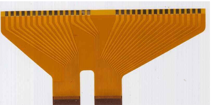
Coverlay flex gets its name from the “coverlay” material that covers the circuit. The coverlay is an insulating dielectric film, usually made from polyimide or polyester. It is applied over the circuitry to prevent shorts, environmental damage, and other issues. The conductive traces are etched or printed onto the base polyimide film. Then the coverlay is laminated on top of the traces using adhesive and heat.
Coverlay protects the copper traces from oxidation and abrasion. It also prevents electrical shorts between tightly spaced conductors. The coverlay dielectric provides insulation for the circuit and isolates different electrical potentials. Coverlay flex allows components to be mounted directly to the circuit through openings in the coverlay. This eliminates the need for rigid boards. The thin profile of coverlay flex allows the circuit to take on 3D shapes.
Benefits of Coverlay Flex
- Extremely thin and lightweight
- Highly customizable using different coverlay materials
- Can flex and bend repeatedly without failure
- Durable and resistant to environmental conditions
- Allows dynamic movement and 3D configurations
- Easily integrated with components through openings
- No need for rigid printed circuit boards
- Reduced assembly costs compared to rigid-flex circuits
Coverlay flex is a high-performance and reliable interconnect solution. The tight lamination between layers prevents delamination over time. Coverlay flex is extremely thin, with some types having a total thickness under 1 mm. This allows the circuit to roll up or conform around products. With certain adhesive types, coverlay flex can operate in a wide temperature range. The flexibility also absorbs mechanical stress and vibration that would fracture a rigid board.
Coverlay Flex vs. Rigid-Flex
Coverlay flex differs from rigid-flex circuits, which combine rigid board sections with flexible connects. Rigid-flex requires complex processing to integrate the different materials. This includes precise mechanical drilling and routing. Rigid sections provide mounting stability and component placement. But they limit theflexibility and increase thickness.
Coverlay flex uses only flexible materials. The polyimide base film and coverlay are both thin, bendable dielectrics. This allows coverlay flex to take on truly 3D shapes. The fold radius can be as tight as 0.10 mm for standard polyimide. Coverlay openings allow direct component attachment without rigid sections. Dynamic flexing, rolling, and folding are possible throughout the entire circuit.
Coverlay flex simplifies the PCB fabrication process. No mechanical drilling orcomplex lamination steps are required. The flexible materials make it easy to manufacture roll-to-roll. Die-cutting can create any outline shape. This supports prototyping and lower volume production. Coverlay flex eliminates the assembly costs of attaching multiple rigid boards. The flexible circuit can interface directly with components and connectors. Whole sections can also flex out of the way during assembly or servicing.
Coverlay Flex Circuit Materials
Coverlay flex allows a wide range of material choices for both the base film and coverlay:
Base Films
- Polyimide – Standard coverlay flex base. Offers excellent flex life and temperature resistance. 1-2 mil thickness.
- Polyester – Lower cost alternative to polyimide. Not as heat resistant. 1-5 mil thickness options.
- LCP (Liquid Crystal Polymer) – High frequency circuit support. Extremely stable dielectric properties.
- PEN (Polyethylene Naphthalate) – High strength and stiffness. Ideal for roll-to-roll processing.
- Fluoropolymers – Offer superior chemical resistance for harsh environments.
Coverlay Films
- Polyimide – Most common coverlay, available in 1-3 mil thickness.
- Polyester – Lower cost coverlay option. Not as heat resistant as polyimide.
- LCP (Liquid Crystal Polymer) – Used for high frequency analog flex circuits.
- Acrylic – Hard coating that resists abrasion and chemical damage.
- Nylon – Tough coverlay for excellent flex life and strength.
Coverlay flex offers the ability to select the optimal base and coverlay materials. This supports the performance, flexibility, processing,and temperature requirements of the application. Common configurations are 1-2 mil polyimide base with 1 mil polyimide coverlay. But the circuits can utilize other films for specific demands. For example, polyester base with nylon coverlay provides a low-cost circuit with high durability. Fluoropolymer films offer robust chemical resistance.
Design Considerations for Coverlay Flex
Coverlay flex allows flexible circuit boards to be designed for almost any application. But the flexibility does require accounting for specialized considerations:
- Dynamic flexing – The circuit may need to repeatedly bend and roll during use. The materials and trace design should support long flex life.
- Fold radius – Avoid tight folds that overstress the base film. Use large fold radii, with a minimum bend radius of at least 10 times the total circuit thickness.
- Strain relief – Provide strain relief cutouts or patterns along the flexing sections to absorb mechanical stress.
- Component attachments – Use coverlay openings to attach chips, passives, or connectors directly to the flex circuit. Ensure the adhesive and solder joints can withstand flexing forces.
- Trace routing – Route the traces to keep conductors on the neutral axis during bending. This prevents overstretching the traces on the outer layers.
- Stackup – Use additional flexible dielectric layers to support complex circuitry. Carefully arrange reference planes and ground layers.
- Termination – Provide sufficient space for connecting the flex tails to rigid boards or components.account for misalignment tolerance.
With careful design, coverlay flex can maintain excellent reliability and performance under continual bending. Following best practice guidelines prevents conductor cracking and connections failures.
Coverlay Flex PCB Construction
Constructing the flexible PCB with coverlay involves several fabrication processes:
- Start with the base polyimide or polyester dielectric film.
- Conductive copper traces are formed on the base film through subtractive etching, additive plating, or printing.
- Components or connectors are soldered onto the circuit pads and openings.
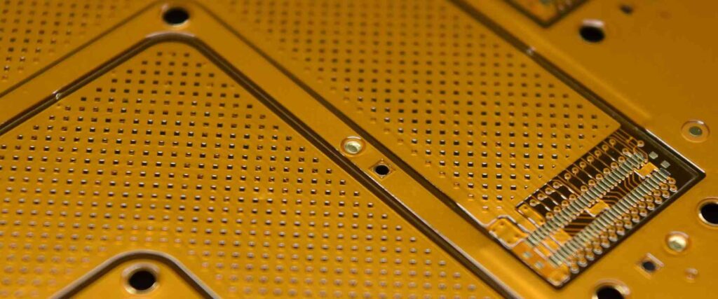
- The coverlay material is precision laminated onto the conductive layer using adhesive activated by heat and pressure.
- Additional layered flexible circuits can be added to create multilayer stackups.
- Openings are made in the coverlay to expose component attachment pads using laser ablation.
- Silkscreen printing can provide markings such as circuit traces, board outlines, and polarity indicators.
- Finally, the completed coverlay flex PCBs are singulated into individual circuits through die-cutting or sawing.
The coverlay lamination and laser ablation steps are key to producing a reliable, high quality flex circuit board. The materials, design, and specialized processing results in flexible PCBs able to withstand millions of flex cycles.
Coverlay Adhesive Options
The adhesive that bonds the coverlay to the base substrate plays a crucial role in the performance and reliability of coverlay flex circuits. There are three main types of adhesive used in coverlay laminations:
- Thermosetting – These permanent adhesives are activated and cured during the heated press lamination process. Offer very strong, durable bonds to withstand flexing. But rework and repairs are difficult.
- Thermoplastic – Activates upon heating but doesn’t fully cure. Allows removing and replacing the coverlay for rework. Provides good bond strength for dynamic flex applications.
- Pressure Sensitive Adhesive (PSA) – The coverlay has a pre-applied adhesive that sticks with applied pressure. Allows easy rework. Bonds are not as robust for continual flexing. Mainly used for multilayer flex stackups.
Choosing the right coverlay adhesive prevents delamination or cracking during flexing. Thermosetting epoxy for single layer boards. Thermoplastic for moderate flex life requirements and some rework ability. PSA for multilayer circuits with minimal flexing.
Coverlay Flex Circuit Applications
Coverlay flex printed circuits support many demanding modern applications:
Wearable Electronics
The lightweight, thin, and flexible nature of coverlay flex makes it ideal for wearable devices. Flexible circuits easily conform to body contours. Polyimide flex circuits allow reliable dynamic bending without fatigue. Coverlay openings or bumps interface sensors and surface mount components directly onto the flex board. Examples include health trackers, medical monitors, smart clothing, virtual reality systems, and athletic performance devices.
Medical Electronics
Medical devices like patient monitors, pumps, and implants must withstand continual dynamic flexing. Coverlay flex circuits enable miniature, comfortable, and biocompatible solutions. The thin profile is easily integrated into devices or attached to tubing. Polyimide withstands sterilization. Flexible circuits improve reliability compared to wired harnesses. This helps prevent critical device failures.
Vehicle Electronics
Vehicles utilize flex circuits for dashboard electronics, power systems, sensors, control modules, and engine components. The vibration resistance prevents solder joint cracking. Flex-to-board connectors absorb stress. Flex circuits survive the high underhood temperatures. Durability allows long product lifetimes. Coverlay flex eliminates bulky wire harnesses for lighter vehicles and design flexibility.
Consumer Electronics
Many consumer products benefit from coverlay flex’s small size and dynamic capability. Laptop and device motherboards use flex to connect components. Displays integrate flex circuits for LED backlighting. printers employ flex sensors and interconnects. mice, keyboards, game controllers, cameras, appliances, and more use coverlay flex circuits inside. This allows innovative moving designs and mechanisms.
Lighting
LED lighting relies on flex circuits to create lightweight and reliable interconnects. The thin circuits easily fit into tight spaces. Coverlay flex withstands high temperatures for interior and outdoor lighting applications. Dynamic flexing survives continual movement, vibration, and environmental factors.
Defense & Aerospace
Avionics, satellites, and defense systems operate in extreme environments. Flexible circuits withstand intense vibration and thermal cycles. The durability improves reliability for mission-critical devices. Coverlay polyimide withstands high temperatures. Flex circuits allow design innovations like roll-out solar arrays. The reduced size and weight benefits aerospace applications.
Other Industries
Many additional markets utilize coverlay flex printed circuits:
- Robotics – for movement capabilities and sensory integration
- Industrial – instruments, automation, and control systems
- Energy – solar, oil drilling sensors, wind power
- Packaging – 3D circuits integrated into product packaging
Any application with demands for a highly reliable, dynamic, and adaptable circuit will benefit from the advantages of coverlay flexible PCBs.
Summary of Coverlay Flexible Circuit Boards
Coverlay flex PCBs provide a modern interconnect solution using polyimide or polyester base films laminated with a thin coverlay over the traces. The technology offers:
- Extreme flexibility, bend radius down to 0.10mm
- Durable construction to survive millions of flex cycles
- Thin, lightweight, and customizable for any application
- Integration of components directly onto the flex board
- Simplified design and manufacturing compared to rigid-flex
- Support for roll-to-roll processing and high volume production
- Cost effective for lower complexity compared to multilayer rigid boards
Coverlay flex allows innovative and reliable electronic designs not possible with rigid boards. The flexible circuits are impacting product development across industries from consumer wearables to advanced aerospace systems. Continued improvements in flexible PCB materials, fabrication, and component integration will drive coverlay flex as the future interconnect solution for dynamic and moving electronics.
Frequently Asked Questions
What is the typical thickness of coverlay flex circuits?
Coverlay flex thickness depends on the material choices. Typical constructions are:
- 1 mil polyimide base / 1 mil polyimide coverlay: Total thickness around 3 mils (0.075mm)
- 2 mil polyimide base / 2 mil polyimide coverlay: Total thickness around 6 mils (0.15mm)
- 2 mil polyester base / 1 mil polyester coverlay: Total thickness around 5 mils (0.13mm)
So standard coverlay flex thickness ranges from 3 mils to 6 mils. Even thinner constructions are possible for maximum flexibility.
What are common coverlay opening shapes?
Round openings are most common, made using a laser or mechanical punch. This allows clearance for soldered component terminations like BGA balls or gull wing leads.
For connectors and some sensors, rectangular or slotted openings may be used.going around components instead of openings is also an option. Special star shaped or “X” patterns can provide stress relief during dynamic flexing.
How many flex cycles can coverlay flex withstand?
Properly designed coverlay circuits can reliable withstand millions of flex cycles, such as:
- Polyimide coverlay flex: 5,000,000+ cycles
- Polyester coverlay flex: 1,000,000+ cycles
Factors like material type, trace design, and bend radius determine the overall flex life. Dynamic testing under application loads is recommended to verify performance.
Can components be mounted on both sides of coverlay flex?
Yes, double-sided component attachment is possible with coverlay flex. Openings in the top and bottom coverlay allow mounting to pads on both sides. This provides design flexibility to place components as needed.
Vias or plated through holes make electrical connections between the layers. Careful thermal management of double-sided populated boards is required. Strategic placement helps avoid excessive heat concentration.
How are coverlay openings formed?
The most common methods are:
Laser ablation – A CO2 laser burns away the desired opening patterns in the coverlay after lamination. Offers high accuracy and resolution down to around 0.125mm.
Mechanical punch/routing – Steel rule dies or routed tools cut out larger openings in the coverlay material prior to lamination. Typically >2mm in size. Provides lower cost for high volumes.
How are coverlay flex circuits tested?
Electrical testing checks continuity, resistance, and insulation. Automated optical inspection looks for defects. Flexural endurance testing prescribes repeated bending cycles to validate flex life. Environmental testing puts the circuit through thermal shock, vibration, and humidity loads.
Many tests align with standards like IPC-6013 and IPC-7095 for qualification. Reliability testing levels and durations are determined based on the application requirements.
Conclusion
Coverlay flex printed circuits provide the ideal solution for flexible, dynamic, and miniaturized electronic devices. Polyimide-based constructions offer proven resilience against cracking and delamination over millions of bend cycles. As electronic products continue getting smaller, lighter, and more wearable, coverlay flex enables new possibilities not attainable with rigid boards. Further advancements in materials, fabrication methods, and 3D component integration will solidify coverlay flex circuits as the future of interconnect technology.


Leave a Reply