Flexible printed circuit boards (FPCBs), also known as flex circuits, are a type of printable circuitry that can bend and flex. They provide many advantages over traditional rigid printed circuit boards (PCBs) including flexibility, durability, weight savings, space savings, and design freedom. This article will provide an in-depth look at flex circuits covering their design, manufacturing, applications, benefits, and future outlook.
What are Flex Circuits?
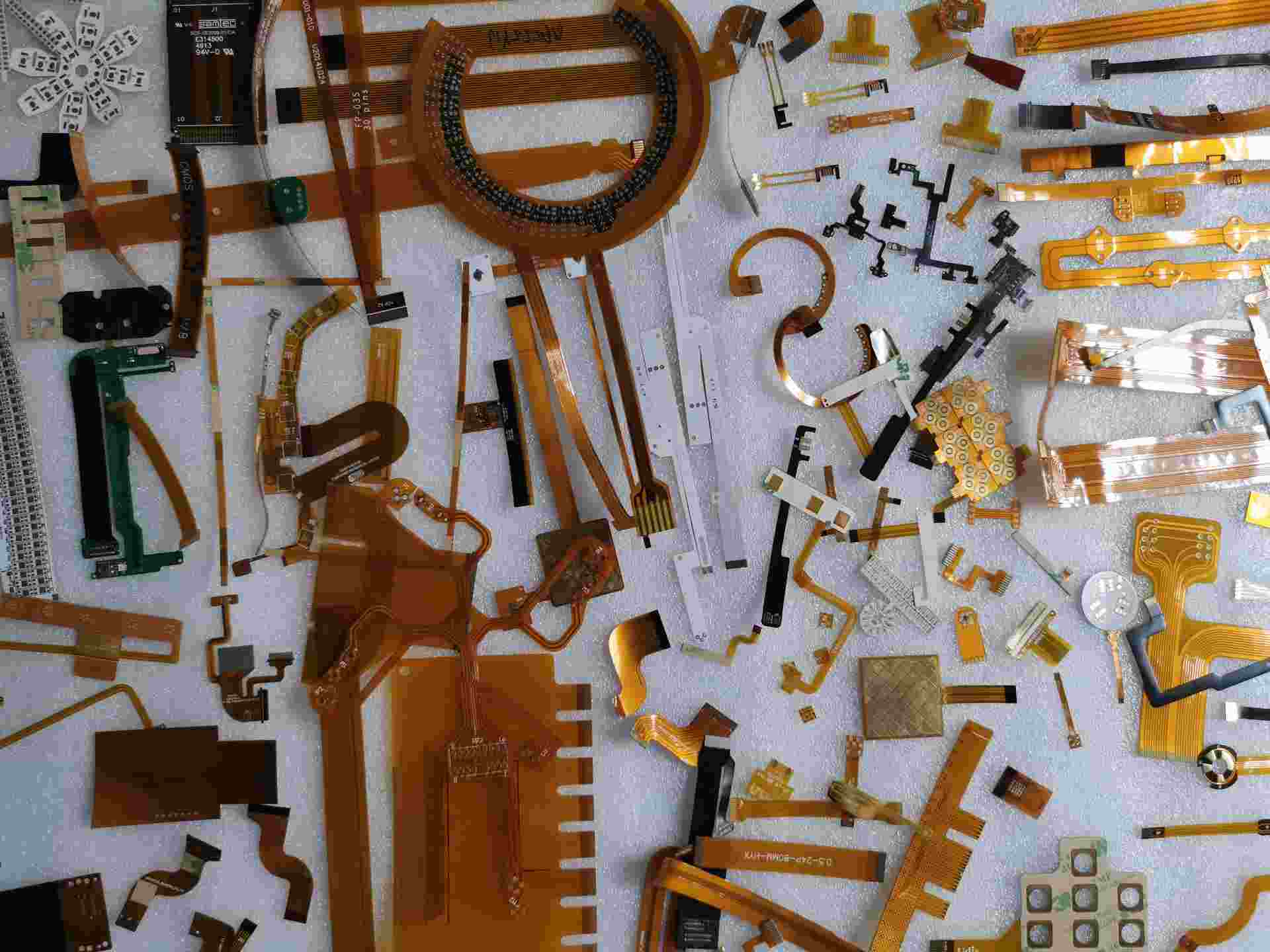
A flex circuit or flexible printed circuit is a technology for assembling electronic circuits by mounting electronic devices on flexible plastic substrates such as polyimide or polyester. The circuits are made using conductive copper laminates etched into desired patterns and bonded to the substrate. The components are then soldered onto the conductive traces.
Flex circuits can be screened printed silver circuits as well. They provide electrical connections between components while still retaining flexibility and durability. They can be wrapped around edges and molded into different shapes to accommodate space and design requirements.
Design and Composition
Flex circuits consist of three fundamental components:
- Base Material – Made up of a flexible plastic film substrate such as polyimide, polyester, polyethylene naphthalate (PEN), or polyethylene terephthalate (PET). Polyimide is commonly used.
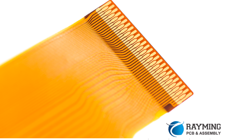
- Conductive Traces – Usually copper foil, which is laminated onto the base substrate and etched into circuit patterns. Other conductive materials like gold, nickel, and tin may also be used.
- Cover Layer – A protective layer of adhesive-backed flexible plastic film, like polyimide. It shields the conductive traces.
Other secondary components can include:
- Stiffeners – Applied to strengthen and support flex circuits if they need to maintain a particular shape.
- Terminations – Connectors or points to attach electronic components and integrate circuits with cables or PCBs.
- Adhesives – Bond flex layers together. Can also provide electrical insulation.
- Solder mask – Coats exposed traces to prevent solder bridging between conductors.
- Printed graphics – Identifiers, symbols, logos etc. printed on flex circuit surfaces.
- Vias – Holes drilled in the substrate to allow connections between layers in multilayer flex stacks.
Manufacturing Process
Flex circuits are manufactured using the following steps:
- Design circuit layout – Done with CAD software accounting for electrical needs and physical demands.
- Etch copper patterns – Photolithographic process transfers layout onto copper-laminated base substrate.
- Die cut – Individual flex circuits are cut from large etched sheets.
- Assemble components – Passive components and connectors are soldered directly onto circuit paths.
- Encapsulate – Conformal coatings applied for insulation and protection.
- Test – Each completed flex circuit is electrically tested.
- Final finishing – Additional stiffeners, shields or graphic overlays added as needed.
Benefits of Flex Circuits
Compared to rigid boards, flex circuits provide many significant advantages:
Flexibility
The flexible and bendable nature of flex circuits allows them to be used in applications where standard rigid PCBs would fail or be difficult to integrate. They can flex and conform to curved surfaces, twist and bend around obstructions, and dynamically flex during movement, vibration or impacts.
Thin and Lightweight
Flex circuits use extremely thin substrate materials making them thinner and lighter than rigid boards. Weight savings of up to 70% can be achieved using flex circuits depending on design.
Space and Volume Savings
Thinness and flexibility allow flex circuits to fit into tight spaces where rigid boards cannot. They require less surface area and volume, enabling smaller products and packages.
Reliability
Flex circuits offer reliable connections as traces stay bonded to the substrate even when flexing instead of connecting through solder joints prone to fatigue and failure. They are extremely durable compared to rigid boards.
Noise Reduction
Their thin profile and close proximity to parent electronics minimizes noise. Shorter traces act like transmission lines and reduce interference.
Design Freedom
Flexibility allows three-dimensional circuitry design with traces folding, wrapping and conforming around products. Rigid-flex combinations integrate rigid components onto flex substrates for even more design freedom.
Component Integration
Components can be surface-mounted directly onto flex circuits. Flip chip or wire bonding integrated circuits (ICs) can also be mounted for high-density interconnects.
Cost Savings
Fewer connectors, joints, and processing steps required results in cost savings. Simplified assembly also reduces labor costs. Volume manufacturing provides opportunities for scaling cost benefits.
Improved Production
Continuous etching of sheets allows high-volume production. Components can be pre-attached to eliminate secondary soldering and assembly steps.
Flex Circuit Applications
Some common applications that benefit from using flex circuits include:
Consumer Electronics
Wearable devices, mobile phones, tablets, cameras, game controllers, and VR headsets all use flex circuits for interconnections. Flex cables enable motion while maintaining circuits.
Automotive Electronics
Flex circuits handle vibration in critical automotive subsystems like brake controls, engine sensors, power steering, lighting, seats, mirrors and more.
Medical Electronics
They provide flexible interconnections and circuitry in body-worn health monitors, implants, patches, and medical instruments which require durability and reliability.
Industrial Electronics
Flex circuits withstand vibration and repeated flexing in machinery. Robotics, factory automation systems, scales, and measurement instruments employ them.
Aerospace and Defense
Rugged flex circuits withstand shock, vibration, temperature extremes, radiation and other environmental stresses in spacecraft, jets, weapons systems and avionics.
Computing
HDD suspensions, keyboards, printers and other peripherals employ flex circuits for interconnections that undergo frequent dynamic bending.
Types of Flexible Circuits
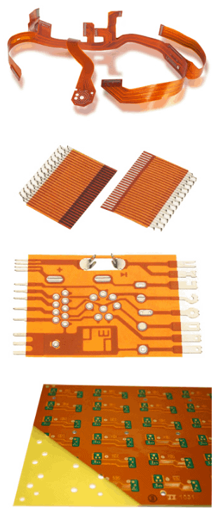
There are several variations of flexible circuits available, with each type suited to specific applications:
Single Layer Flex Circuits
A basic flex circuit with a single layer of conductors etched onto a dielectric substrate. Suitable for simple low-density interconnections.
Double Layer Flex Circuits
Two conductor layers bonded to both sides of the substrate. Provides more connection capacity and allows crossing traces without contact.
Multilayer Flex Circuits
Have 3 or more layers of conductors separated by insulating dielectric substrates and interconnected by plated through-holes or vias. Enables complex high-density interconnections.
Rigid-Flex Circuits
Integrate rigid FR4 PCB sections with flexible circuits to provide stability, spacing, and components mounting. Circuits can have both rigid and flex sections.
Flexible Ribbon Cables
Multiple parallel conductors extruded in a flat cable assembly that can be bent and twisted. Used to interconnect PCBs.
Flexible Shielded Cables
Use outer foil or braided mesh shields to protect signals from EMI/RFI noise. Common in aerospace, medical and telecom applications.
Flexible PCBA Cables
Have connectors pre-soldered onto flex circuit cable ends to plug into PCB sockets. Provide extendable interconnections.
Future Outlook for Flex Circuits
The flexible printed circuit board market has been growing steadily for years due to the expanding applications in consumer electronics and miniaturization trends. Here are some projections on the future of flex circuits:
Market Growth
The global flexible printed circuit market size is estimated to grow from $13.5 billion in 2022 to $28 billion by 2030, at an 8.5% CAGR.
Materials Innovation
Advances in substrate materials, conductors, adhesives and coatings will enable flex circuits to handle more extreme conditions. Optical waveguides may also be integrated.
Design Evolution
Improved CAD tools and design for manufacturing guidelines will enable more complex flexible circuits and rigid-flex configurations tailored to products.
Applications Diversification
Emerging applications in medical technology, solar power, IoT devices, wearables, and sensors will drive adoption across more industries.
High-Density Interconnects
New fabrication processes allow finer circuit features below 25 microns enabling denser interconnects. Embedded actives and passives components will also increase.
Manufacturing Improvements
Automation technology will improve volume production. Growing use of additive processes could enable on-demandflex circuit fabrication.
In summary, the design freedom, durability and miniaturization possible with flexible printed circuit boards ensures they will become even more indispensable in electronics manufacturing in the future.
Flex Circuits Frequently Asked Questions
Here are answers to some common questions about flex circuits:
Q: What are some typical layer counts for multilayer flex circuits?
A: 2 to 12 layers are common, though circuits with up to 30 layers are possible with very fine traces and spacing. 8 layers or more provide high interconnect density.
Q: Can components be mounted directly onto flex circuits?
A: Yes, surface mount devices and packaged ICs are frequently mounted directly onto flex circuits. Through-hole components can also be used with or without drilled holes.
Q: How are connections made between rigid and flex sections?
A: The rigid and flex materials are commonly bonded together using acrylic or epoxy adhesives to form an integrated circuit. Solder, conductive epoxy or mechanical clamping may also connect the sections.
Q: What are some key standards used for flex circuit design?
A: IPC-2223 – Sectional design standard for flexible printed boards. IPC-6013 – Provides qualification and performance specifications. IPC-A-600 – Acceptability standards for flex boards.
Q: Are flex circuits only used for interconnections?
A: No, flex circuits are increasingly used as stand-alone functional circuit boards. A rigid-flex combination can provide a complete electronic subsystem on a single circuit.
Q: Can flex circuits be easily repaired or reworked if needed?
A: Yes, repairs are simpler than on rigid boards since component removal doesn’t require desoldering. Cutting traces or jumper wires allow circuit modifications and edits.


Leave a Reply