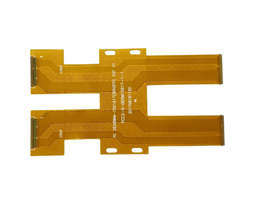
A flexible printed circuit board (PCB) is a type of circuit board made with flexible materials that allow the board to bend and flex without damage. Flexible PCBs go by several common names, including:
Flexible Circuit Board
The most generic name is simply “flexible circuit board” or “flex circuit.” This umbrella term refers to any PCB made with flexible materials able to dynamically flex and bend along one or multiple axes.
Flex circuits retain all the same characteristics as rigid PCBs. They contain conductive traces, pads, and other components. But their flexible construction sets them apart.
Flex PCB
“Flex PCB” is an abbreviated name frequently used to refer to this type of circuit board. The “flex” portion comes from the board’s flexible nature.
This shortened name provides a quick and convenient way to refer to the technology. If someone mentions a “flex PCB,” it’s clear they are talking about a flexible printed circuit board.
Flexible Printed Circuit
Another common name is “flexible printed circuit” or “FPC.” The words “printed circuit” in the name refer to the conductive traces printed or etched onto the flexible base material.
“Flexible printed circuit” emphasizes that, while the circuit board can bend, it is still a printed circuit like a rigid PCB. The “flexible” adjective distinguishes it from rigid boards.
Flexible Printed Wiring
Some industries refer to flex circuits as “flexible printed wiring” or “flexible printed wiring boards.”
The word “wiring” refers to the conductive traces on the board that connect components — like wires in a breadboard or integrated circuits. The “printed” portion again refers to the way traces get applied to the flexible base material.
Together, the name focuses on the flex circuit’s fundamental purpose: providing flexible wiring to connect electronics.
Flexible Flat Cable
Another name is “flexible flat cable,” or “FFC.” This refers specifically to single-layer flex circuits.
The word “flat” contrasts the thin, flat shape of an FFC versus traditional, multi-strand wiring cables. FFCs provide similar connections in a flat, flex circuit package.
Factors in Flexible PCB Names
As the multiple names demonstrate, flexible PCB terminology focuses on three key aspects of the technology:
- Flexible Construction: Emphasizing words like “flexible,” “flex,” and “bendable” focuses on the dynamic physical nature of the boards.
- Printed Circuit: Terms like “printed circuit” and “printed wiring” refer to the conductive traces etched or printed onto the base material. This construction method is what distinguishes PCBs from other electronics wiring.
- Connectivity: Names like “wiring” and “flat cable” refer specifically to the flex circuits’ intended purpose – providing electrical connections in electronics devices.
While the most generic term remains “flexible circuit board,” the other names highlight important defining characteristics. Engineers, designers, and manufacturers choose whichever terminology best fits their particular context and audience. But all the names refer to the same basic technology.
Key Attributes of a Flex PCB
To understand flexible PCB names more clearly, it helps to review the key attributes that set flex circuits apart from rigid boards:
- Flexible substrate – Made with a thin, flexible plastic base layer that allows bending without damage. Polyimide is a common base material.
- ** Conductive traces** – Usually made from copper, etched or printed onto the flexible base material to create electrical connections.
- Dynamic flexing – Able to repeatably bend and flex without cracks or breaks in traces.
- Lightweight – Extremely thin and lightweight compared to rigid PCBs.
- Durable – Can endure millions of dynamic flex cycles. Optimized for flex applications.
- Compact – Thin profile allows fitment into tight spaces a rigid board could not fit.
Flex circuits get their name from the combination of printed circuit connections and flexible physical construction. When designed properly, they provide the connectivity of rigid boards with the bendability of wiring.
Key Applications of Flexible PCBs
The applications that benefit from flexible PCBs fall into three general categories:
1. Dynamic Flex Applications
Any application where the circuit board must dynamically bend during use requires a flex circuit. For example:
- Wearable devices
- Robotics joints
- Foldable electronics
- Hinges and displays
In these examples, a rigid PCB would crack or break with any bending or flexing. Flex circuits are essential to provide circuitry that can survive extensive dynamic movement.
2. Space-Constrained Applications
The thin profile of flex circuits allows them to fit into extremely tight spaces where a rigid board won’t fit. Common examples include:
- Mobile phones
- Laptops and tablets
- Digital cameras
In small consumer electronics, flexible PCBs allow more components and functionality to be packed into the compact housing.
3. Weight-Sensitive Applications
Because flex circuits are extremely lightweight, they’re used when weight is a key consideration. For instance:
- Aerospace and avionics
- Motorsports
By reducing weight, flexible PCBs can improve performance metrics like fuel efficiency and speed.
Understanding common flex circuit applications makes their purpose and name more clear – flexible printed wiring for electronics in motion.
Flexible PCB Construction and Materials
To create a flex circuit’s flexible construction, manufacturers use specialized materials and fabrication processes. Here are some of the key elements:
Substrate Materials
The flexible base material or “substrate” is usually a thin polyimide or polyester film. These plastics retain their mechanical strength and electrical insulating properties even when bent. Typical thicknesses range from 12.5 μm to 150 μm.
Conductors
Conductive traces are fabricated from rolled annealed copper foil, usually 18 μm to 70 μm thick. Traces are etched or printed onto the base substrate.
Coverlayer
A thin cover layer of adhesive dielectric protects the conductor traces from damage. Polyimide is commonly used as coverlayer material.
Lamination
Multiple layers of substrate, adhesive, and copper foil are stacked and laminated under heat and pressure to create the flex circuit board.
Stiffeners
For sections that won’t flex during use, a rigid stiffener made from FR4 or polyimide can be added for structural support.
Proper material selection and fabrication provides both flexibility and electrical connectivity in the finished board.
Flex Circuit Design Rules
To create a functional, durable flexible PCB, engineers follow specific design rules during layout. These rules optimize the design for flexing:
- Use large bend radii – Avoid tight folds with small radii that concentrate stress.
- Avoid fracturing traces – Design wide trace widths and spacing to prevent conductor cracks.
- Minimize layers – Stacking too many layers can inhibit flexibility.
- Protect components – Use glue or stamps to hold small components during bending.
- Anchor terminations – Secure points connected to stiff sections to prevent tears.
Following best practices for flexible PCB design is crucial to enable dynamic bending without compromise.
Flexible Circuit Board vs Rigid PCB
While flex circuits share similarities with rigid PCBs, their construction and capabilities create key differences:
| Flexible PCB | Rigid PCB |
|---|---|
| Flexible substrate | Rigid substrate (usually FR4) |
| Thin profile | Thick profile |
| Dynamic flex capability | No flex capability |
| Folds into small spaces | Limited by large size |
| Lightweight | Heavier |
| Complex fabrication | Simpler fabrication |
| Higher cost | Lower cost |
In summary, flex PCBs provide dynamic flexibility while rigid PCBs offer simpler construction at a lower price. Engineers weigh the trade-offs between both technologies when selecting the optimal circuit board type for an application.
Flexible PCBs FQA
Here are answers to some frequently asked questions about flexible PCBs:
What are the typical substrate materials used in flex PCBs?
The most common substrate materials are polyimide (Kapton) and polyester (PET). They provide the optimal balance of flexibility, electrical insulation, chemical resistance, and temperature tolerance.
What are some key differences between rigid FR4 PCBs and flex circuits?
Key differences include the flexible substrate material, overall thickness, weight, cost, dynamic bend capability, complexity of fabrication, and design rules.
What are some examples of flexible PCB applications?
Flex circuits are used in wearable devices, consumer electronics, automotive, aerospace, robotics, and medical devices – anywhere lightweight, dynamic, or space-constrained circuitry is needed.
How many times can a flex PCB be dynamically flexed before failing?
Properly designed flex circuits can reliably withstand millions of flex cycles before traces may eventually fracture. Flex life depends on multiple design factors.
What are some best practices to follow when designing a flexible PCB?
Use large bend radii, wide traces/spacing, minimal layers, component protection, and anchor points. Following flex-specific design rules is critical.
Conclusion
Flexible printed circuit boards go by several common names, all referring to their signature blend of a bendable, flexible substrate with printed conductive traces. The many names each highlight important attributes of flex circuit technology related to flexibility, connectivity, and fabrication methods.
Engineers choose flex PCBs when an application requires dynamic motion capability, tight space constraints, or lightweight construction. When designed using specialized materials and layout practices, flex circuits can provide millions of maintenance-free bend cycles in demanding flex applications ranging from wearable gadgets to advanced aerospace systems.


Leave a Reply