Introduction to Flex Boards
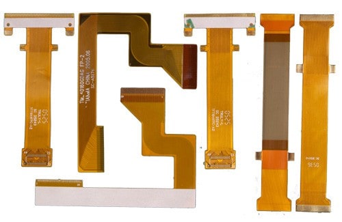
Flex boards, also known as flexible printed circuit boards (FPCBs), are a type of printed circuit board made with flexible substrate materials. This allows the board to bend and flex while still maintaining electrical connections between components. Flex boards provide several advantages over traditional rigid PCBs:
- Can conform to curved or irregular shapes
- Good for dynamic flexing applications
- Lightweight and thin profile
- Allows for compact product designs
- Can access confined spaces and fold into small sizes
- Less prone to cracking under physical stress
Flex boards are commonly used in consumer electronics, medical devices, industrial equipment, aerospace systems, and automotive applications. The flexible nature enables their use in many innovative ways not possible with rigid boards.
Growth of Flex Board Market
The global market for flex boards has seen steady growth over the past decade. According to industry analysis, the flex circuit market was valued at around $12.6 billion in 2017. It is projected to grow at a CAGR of over 5% through 2025, reaching nearly $18 billion.
Several factors are driving the increased use of flex boards:
Miniaturization of Electronics
As consumer and industrial devices continue getting smaller, flex boards allow manufacturers to fit more functionality into tight spaces. The thin, bendable nature makes them ideal as electronics shrink to microscopic sizes.
Increased Processing Capabilities
Improvements in conductive materials and manufacturing processes allow flex circuits to handle more power and data throughput while maintaining flexibility. This enables their use in more robust applications.
Emerging Technologies
New technologies like wearable devices, flexible displays, and medical implants rely on thin, bendable circuit boards to conform to curvy surfaces and move with the human body. The expected growth of these markets will drive flex board demand.
Automotive Applications
Weight reduction is key for automotive designs. Flex circuits allow for wiring consolidation, replacing bulky wire harnesses and enabling lighter-weight, compact modules. Vehicles now incorporate flex boards in everything from dashboard displays to seat heaters.
Flex Board Materials and Construction
Flex boards can be constructed using a range of flexible substrate materials, conductive tracing, cover layers, and stiffener components.
Substrate Materials
The flexible substrates commonly used include:
- Polyimide: This plastic film offers excellent heat resistance and high flexibility. Kapton is a well-known brand of polyimide film used for flex circuits.
- Polyester: Boasts good flex life and electrical insulation properties. Often used as an economical option.
- PEN: Polyethylene naphthalate has high-temperature resistance, chemical resistance and dimensional stability. Used for more rugged applications.
- Fluoropolymers: PTFE film offers robust chemical resistance for flex boards in demanding environments.
Conductive Tracing
The conductive traces that carry electric current are typically made from:
- Copper: Most common choice, allows for fine trace widths and pads. Can be rolled annealed copper for maximum flexibility.
- Silver: More expensive but highest conductivity. Often used for high-frequency or high-current applications.
Coverlayers
Additional polymer layers can be laminated over the top of traces to provide protection. Polyimide, PEN or PET films are commonly used. Specialized coverlayers include:
- EMI shielding: Block electromagnetic interference.
- Adhesives: Provide tackiness for components or heat dissipation.
Stiffeners
For sections that require rigidity, additional layers are added:
- Banana bars: Strip-like copper stiffeners that reinforce select areas.
- Rigid sections: Polymer sheets laminated to flex layer. Often used for component mounting.
Flex Board Design Considerations
Designing a successful flex board requires accounting for the unique requirements of flexible circuits. Key considerations include:
- Bend radius: Avoid too tight of bends that can fracture traces.
- Conductor layout: Ensure conductors bend axis is oriented properly.
- Layer stackup: Optimize arrangement for needed capabilities.
- Connection interfaces: Manage transitions between rigid and flex sections.
- Dynamic flexing: Accommodate repeated bending, twisting, etc.
- ESD protection: Prevent electrostatic discharge damage.
Proper design is critical to avoid flex circuit failures like conductor cracks or delamination.
Flex Board Assembly Technologies
Assembling components onto flex boards requires specialized processes adapted for their flexible nature:
Soldering
Reflow soldering is commonly used but requires careful fixturing to avoid damaging the thin, flexible board during heating. Soldering irons need temperature-controlled tips.
Adhesives
Conductive epoxies securely bond components while maintaining electrical connections on flexing boards. Anisotropic adhesives only conduct electricity in the vertical direction.
Press-fit Interconnects
Spring-loaded pins compressed into plated through holes create gas-tight, vibration-resistant connections while allowing flexing motions.
Welding
Laser welding permanently welds component terminals onto traces without solder or adhesives. No heating helps avoid damage.
Conclusion
Flex printed circuit boards offer unique advantages for miniaturized, compact electronics and products requiring dynamic bending capabilities. Advancements in materials, fabrication technologies, and design tools will enable increased use of flexible circuits and drive substantial market growth over the coming decade across many industries. With their versatility and reliability, flex boards are positioned to become integral components as electronics become further integrated into everyday products and services.
Flex Board Electronics FQA
What are some key benefits of using flex boards versus rigid boards?
Some of the main benefits of flex boards compared to standard rigid printed circuit boards (PCBs) include:
- Flexibility – can bend, twist, fold to fit product requirements
- Thinner, lighter weight and more compact
- Withstands vibration, shock, repeated motion
- Can access confined spaces and fold into small products
- Conforms to curvy and irregular shapes
- Can connect moving components
- Often simplifies wiring and consolidates connections
How are flex boards manufactured?
There are several specialized techniques used to fabricate flex boards:
- Photolithography prints the circuit traces using an etching process similar to rigid PCB fabrication. This allows fine trace widths.
- Laser direct structuring (LDS) uses lasers to activate polymer surfaces for electroless copper plating.
- Laser or mechanical micromachining cuts traces from metal-clad polymer films.
- Printed electronics methods like inkjet printing deposit conductive inks.
- Roll-to-roll processing prints repeated circuit patterns on rolls of thin polymer.
What types of products commonly use flex boards?
Flex circuits are found in many types of products including:
- Wearable devices – watches, fitness trackers, health monitors
- Mobile phones, tablets, laptops
- Home appliances and consumer electronics
- Automotive – sensors, control modules, LED lighting
- Medical – imaging equipment, hearing aids, prosthetics
- Industrial – robotics, machine tools, inspection equipment
- Aerospace – satellites, flight controls, engine systems
Anywhere that lightweight, dynamic, or space saving circuitry is needed.
What are some considerations when laying out flex board designs?
Some key layout considerations for flex boards include:
- Avoiding tight bend radii below specified minimums
- Proper conductor orientation for dynamic bending axis
- Managing layer transitions between rigid and flex sections
- Allowing for thermal expansion differences
- Minimizing crossovers between layers
- Providing proper reinforcement in heavily flexed areas
- Accommodating vibration/shock without conductor fatigue
- Incorporating stress relief features
How are components assembled onto flex boards?
Typical flex board assembly processes include:
- Reflow soldering, with precision fixturing and profiling
- Conductive adhesives like epoxies or anisotropic tapes
- Press-fit pins compressed into plated through holes
- Ultrasonic or resistance welding of terminals
- Mechanical connections using clamps or brackets
The assembly process is tailored to maintain reliability despite continuous flexing.


Leave a Reply