Introduction
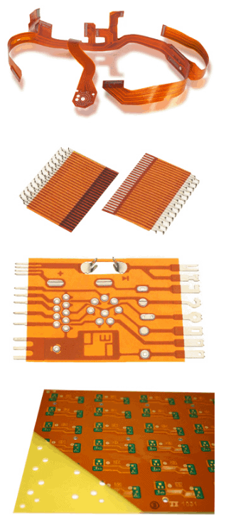
Flexible printed circuits (FPCs), also known as flex circuits, are printed circuits that are made on flexible substrates like polyimide or polyester films. Flex circuits can be bent, folded or twisted to fit into tight spaces and movable applications. They provide solutions for electronic packaging that need to meet space and shape requirements.
Eurocircuits is a leading European manufacturer of printed circuit boards, including rigid and flex PCBs. They offer flex and rigid-flex circuits with or without components in small to large quantities. In this guide, we will look at the capabilities and services Eurocircuits provides for flex PCBs, their design and manufacturing process, and the applications where their flex circuits can be used.
What is a Flex PCB?
A flex PCB or flex circuit comprises of conductors and components that are bonded and printed (etched) onto a flexible dielectric film substrate. The most common base material used is polyimide which is a high temperature resistant polymer. Other base materials include polyester (PET), polyethylene (PE), polytetrafluoroethylene (PTFE) and others.
Flex circuits have the following properties and advantages compared to rigid boards:
- Flexible – can bend, fold and flex repeatedly to fit into small spaces
- Thin, lightweight and takes up less space
- Can be twisted and flexed dynamically in movable applications
- Excellent for wearable electronics and flex-to-fit interfaces
- Capable of 3D wiring for stacking components
- Reliable connections in high vibration environments
- Design freedom and integrated interconnects
Capabilities of Eurocircuits Flex PCBs
Eurocircuits provides comprehensive flex PCB solutions from rapid prototyping services to volume manufacturing. Here are some of their key capabilities:
Flex Layers
- Offer 1 to 12 layers of interconnects
- Typical 2-6 layers, more layers provide higher component density
- Double sided flex most common, allows SMT parts on both sides
- Multilayer flex used for complex layouts
Flex Materials
- Polyimide base materials for flex circuits
- Kapton – most common, high temp and chemical resistance
- Apical – high temperature polymer
- Upilex – UPILEX® offers excellent environmental resistance
- Polyester base materials
- PET / ITO – lower cost but less heat resistance
- Thicknesses range – 12.5μm to 75μm, 50μm most common
- Adhesive options – acrylic, epoxy, heat seal connections
Flex Circuits with Stiffeners
- Flex-rigid PCBs with rigid FR4 stiffeners for mounting strength
- Parts can be mounted on rigid sections for stability
- Eliminates need for separate rigid PCB
Flex PCBs with Components
- SMT assembly – surface mount parts attached by reflow soldering
- Through hole parts – for connectors needing leads on both sides
- Chip-on-flex – bare die/IC direct attachment without packaging
- Flip chip interconnect – direct mounting of flip chips on board
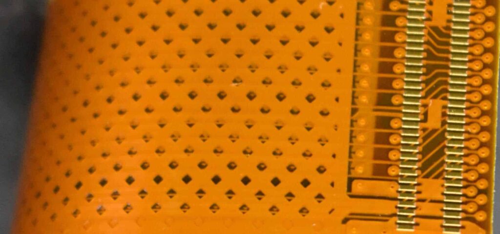
Advanced Flex PCB Capabilities
- Fine line/space to 15μm trace/space
- 4 mil hole registration and smaller microvias
- Controlled impedance flex circuits
- Embedded passives/resistors for size reduction
- Flex-to-rigid transitions and connections
- Flexible circuits with rigidized sections
- Multilayer rigid-flex boards with high layer count (>12)
Prototyping and Quick Turn Services
To support their customers with product design and development, Eurocircuits provides quick-turn prototyping services:
- 24 hour Express Service for same day shipping
- 48 hour prototypes (2 day production)
- Engineering change order (ECO) in 5 working days
- Small series starting 1 piece
- No additional costs for prototype quantities
This enables rapid design iterations, verification and testing with flex PCB samples.
Design Considerations for Flex Circuits
While more design freedom is available with flex PCBs compared to rigid boards, certain considerations should be kept in mind:
Dynamic Flexing – The flexing area should be sufficiently large to avoid very acute bending radii. Strain relief openings at junctions of rigid-flex are recommended.
Component Placement – Avoid placing heavy components in flexing zones. Components are best placed near stiffeners or in rigid sections.
Adhesives – Use flexible adhesives to attach components and avoid rigid glues. Flexible solders, conductive epoxies can be used.
Trace Routing – Avoid traces perpendicular to the bend axis. Plan trace direction parallel to the bend radius.
Board Stiffness – Adding more copper layers or thicker base materials increases stiffness. Balancing flexibility and rigidity is key.
Following these guidelines will help create robust, reliable flex circuit designs that have a long operating life. Eurocircuits engineers can provide additional design advice for your specific application requirements.
Manufacturing Process for Flex PCBs
Eurocircuits uses the latest processes, advanced equipment and automation to manufacture high quality flex PCBs. Here is an overview of the typical manufacturing process:
1. Design – Customer provides Gerber design files which are checked by Eurocircuits engineers. Feedback on design for manufacturing (DFM) improvements is provided.
2. Material Lamination – Copper foils are laminated onto flexible dielectric substrates like polyimide or polyester films. Multilayer boards have alternating core films and adhesive layers bonded under heat and pressure.
3. Photoimageable Processing – Dry film photoresists are applied on the copper layers and then imaged using an advanced direct imaging (DI) technique. This creates an exact mask for etching conductors.
4. Etching – The exposed copper is etched away chemically leaving only the designed conductor traces/pads.
5. Stripping and Cleaning – The dry film is stripped away and the boards are cleaned. This leaves behind the circuit pattern on the flex board.
6. Electrical Testing – Each board is electrically tested using flying probe or bed-of-nails testers. This verifies continuity of traces/pads.
7. SMT Assembly – Surface mount components are precisely placed and soldered to the boards using SMT assembly lines. For double sided flex, this is done on both sides.
8. Quality Inspection – Multiple quality inspections under microscopes check assembly quality and solder joint integrity. X-Ray inspection can detect shorts/opens.
9. Final Testing – Each completed board again undergoes open/short circuit testing followed by functional testing if required.
10. Shipping – The finished flex PCBs are packed with anti-static protection. They are shipped via express couriers globally.
Eurocircuits uses fully automated equipment, strict process controls and quality assurance at each process stage. This results in the highest quality flex PCBs delivered on-time to their customers.
Applications of Flex Circuits
The unique properties of flex PCBs make them very useful across many products and applications:
Consumer Electronics
Wearables, smartwatches, fitness bands, AR/VR headsets, displays
Medical
Hearing aids, insulin pumps, ultrasound transducers, implantables
Automotive
Automotive cameras, car sensors, LED lighting, infotainment systems
Aerospace and Defense
Avionics systems, missiles, satellites
Industrial
Robotics, instrumentation, automation systems
Here are some examples of products where Eurocircuits’ flex PCBs are being used successfully:
- Wearable devices – Flex circuits for smartwatch PCBs, health monitoring bands
- Automotive camera – Flexible camera PCBs for surround view systems
- Industrial robotics – Flexible motor driver boards for robot arms
- Medical devices – Multilayer flex circuits for hearing aid electronics
- Aviation systems – High speed rigid-flex with >12 layers
The wide applicability of flex PCBs enables innovative packaging for advanced miniaturized electronic products in many industries.
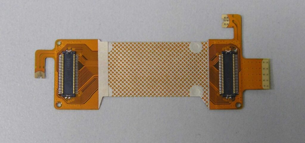
Rigid-Flex PCBs
Rigid-flex PCBs provide a combination of rigid and flexible substrates in a single circuit board solution. This allows rigid support for connectors/components along with dynamic flexing capability.
Eurocircuits offers both single-sided and double-sided flex rigid boards. The rigid sections are made of standard FR4 material and traditional PCB construction. The flex and rigid portions are etched together in a single PCB panel for reliability.
Key benefits of Eurocircuits rigid-flex boards:
- Eliminates connectors between rigid and flex sections
- Allows high layer count >12 layers
- Components can be selectively placed on rigid areas
- Enables 3D packaging and compact design
- Flex-to-rigid transitions with matched TCEs
- Vias can transition between rigid and flex sections
Eurocircuits’ advanced rigid-flex technology enables solutions not possible with separate rigid and flex boards. Their engineers can advise on ideal rigid-flex designs for your application during the design stage.
FQA on Eurocircuits Flex PCBs
Here are answers to some frequently asked questions about Eurocircuits’ flex PCB capabilities:
Q: What are the minimum/maximum dimensions for flex PCBs?
A: Eurocircuits can manufacture flex PCBs with dimensions from a minimum 25mm x 25mm to a maximum of 510mm x 1000mm panel sizes.
Q: What is the minimum bend radius allowed for the flex circuits?
A: For dynamic flexing applications, minimum bend radius should be >10X the board thickness. For polyimide base material up to 3X thickness static bend is possible during assembly.
Q: Can you do controlled impedance matching on the flex PCBs?
A: Yes, controlled impedance flex PCBs can be fabricated with tight impedance tolerances of ±10%. This includes both single ended and differential pair traces.
Q: What is the typical lead time for delivery of prototype flex boards?
A: Eurocircuits offers 24 hour express service for flex PCB prototypes. Standard lead time for small volumes is 5 working days.
Q: Do you assemble components on the flex PCBs?
A: Yes, Eurocircuits offers full assembly of SMT and through-hole components on flex PCBs in low to mid volumes.
This covers some common queries on Eurocircuits’ flex PCB capabilities. Please contact their engineering team for any additional questions on your specific flex circuit requirements.
Conclusion
Eurocircuits provides a complete end-to-end solution for flex PCBs, from rapid prototypes to volume manufacturing. Their advanced flex and rigid-flex circuit technologies enable miniaturization and innovation for current and next-generation products. With strict quality standards, quick-turnaround and global delivery, Eurocircuits is a reliable flex PCB partner for companies across industries.


Leave a Reply