Introduction to Buck Converters
A buck converter, also known as a step-down converter, is a type of DC-to-DC power converter that efficiently reduces the voltage from a higher level to a lower level. It is widely used in various electronic applications, such as battery-powered devices, power supplies, and voltage regulation circuits. In this comprehensive tutorial, we will dive into the fundamentals of buck converters, their working principles, and how to design and build your own DIY buck converter.
What is a Buck Converter?
A buck converter is a switching regulator that steps down the input voltage to a lower output voltage while maintaining high efficiency. It consists of several key components, including:
- An inductor
- A capacitor
- A diode
- A switch (usually a MOSFET)
- A control circuit
The control circuit regulates the switching of the MOSFET, which alternately connects and disconnects the inductor to the input voltage. This process of rapidly switching the inductor’s connection creates a lower average output voltage.
Advantages of Buck Converters
Buck converters offer several advantages over other voltage regulation methods:
- High Efficiency: Buck converters can achieve efficiencies up to 95% or higher, minimizing power losses.
- Compact Size: The high switching frequency allows for smaller inductors and capacitors, resulting in a compact design.
- Adjustable Output Voltage: The output voltage can be easily adjusted by modifying the duty cycle of the switching signal.
- Low Heat Generation: Due to their high efficiency, buck converters generate less heat compared to linear regulators.
Understanding the Working Principle
To understand how a buck converter works, let’s break down its operation into two stages:
Stage 1: MOSFET ON
When the MOSFET is turned on, the input voltage is connected to the inductor. This causes the inductor to store energy in its magnetic field, and the current through the inductor increases. The diode is reverse-biased during this stage, preventing current from flowing through it.
Stage 2: MOSFET OFF
When the MOSFET is turned off, the inductor’s stored energy is released, and the current continues to flow through the inductor, the capacitor, and the load. The diode becomes forward-biased, providing a path for the inductor current. The capacitor helps to maintain a smooth output voltage by filtering out the ripple caused by the switching action.
The control circuit continuously monitors the output voltage and adjusts the duty cycle (the ratio of ON time to the total switching period) to maintain the desired output voltage level.

Designing a Buck Converter
To design a buck converter, you need to consider several key parameters:
- Input Voltage Range: Determine the minimum and maximum input voltages your converter should handle.
- Output Voltage: Specify the desired output voltage level.
- Output Current: Estimate the maximum load current your converter needs to supply.
- Switching Frequency: Choose a suitable switching frequency based on the desired size, efficiency, and noise considerations.
Once you have these parameters, you can calculate the required values for the inductor, capacitor, and other components using well-established design equations.
Inductor Selection
The inductor is a critical component in a buck converter. Its value determines the ripple current and the converter’s operating mode (continuous or discontinuous conduction mode). A larger inductor value reduces the ripple current but increases the physical size of the converter.
To calculate the minimum inductor value for continuous conduction mode, you can use the following equation:
L_min = (V_out × (V_in – V_out)) / (ΔI_L × f_s × V_in)
Where:
– L_min is the minimum inductor value
– V_out is the output voltage
– V_in is the input voltage
– ΔI_L is the inductor ripple current
– f_s is the switching frequency
Capacitor Selection
The output capacitor helps to smooth the output voltage and reduce the voltage ripple. Its value depends on the desired output voltage ripple and the inductor ripple current.
To calculate the minimum capacitor value, you can use the following equation:
C_min = (ΔI_L) / (8 × f_s × ΔV_out)
Where:
– C_min is the minimum capacitor value
– ΔI_L is the inductor ripple current
– f_s is the switching frequency
– ΔV_out is the desired output voltage ripple
Diode Selection
The diode in a buck converter acts as a freewheeling diode, providing a path for the inductor current when the MOSFET is off. It should have a sufficient current rating and a low forward voltage drop to minimize power losses.
Schottky diodes are commonly used in buck converters due to their low forward voltage drop and fast switching speed.
MOSFET Selection
The MOSFET is the switching element in a buck converter. It should have a low on-resistance (R_DS(on)) to minimize conduction losses and a fast switching speed to reduce switching losses.
When selecting a MOSFET, consider the following parameters:
– Voltage Rating: The MOSFET should have a voltage rating higher than the maximum input voltage.
– Current Rating: The MOSFET should be able to handle the peak inductor current.
– On-Resistance: A lower on-resistance reduces conduction losses and improves efficiency.
– Switching Speed: Faster switching speeds minimize switching losses but may increase electromagnetic interference (EMI).
Control Circuit
The control circuit in a buck converter regulates the switching of the MOSFET to maintain a constant output voltage. There are several control methods, including:
- Voltage Mode Control: The output voltage is compared with a reference voltage, and the error signal is used to control the duty cycle of the MOSFET.
- Current Mode Control: The inductor current is sensed and used as an additional feedback signal to control the duty cycle, providing faster response and better protection against overcurrent conditions.
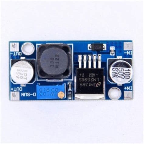
You can use dedicated buck converter control ICs, such as the LM2596 or the TPS62130, which simplify the design process and provide additional features like soft-start and undervoltage lockout.

Building a DIY Buck Converter
Now that we have covered the basics of buck converter design, let’s walk through the steps to build a simple DIY buck converter.
Step 1: Gather the Components
You will need the following components:
– Inductor
– Capacitors (input and output)
– Diode (preferably a Schottky diode)
– MOSFET
– Control IC (e.g., LM2596)
– Resistors and capacitors for the control circuit
– PCB or breadboard for prototyping
Step 2: Design the Circuit
Create a schematic of your buck converter circuit based on the selected control IC and the calculated component values. Refer to the control IC’s datasheet for the recommended circuit configuration and component selections.
Step 3: Assemble the Circuit
Assemble the components on a PCB or breadboard according to your schematic. Pay attention to the component orientations and ensure proper connections between the components.
Step 4: Test and Adjust
Connect the input voltage source and a load to your buck converter. Use a multimeter to measure the output voltage and verify that it matches your desired value. If necessary, adjust the feedback resistors to fine-tune the output voltage.
Step 5: Optimize and Enhance
Once you have a working buck converter, you can optimize its performance by:
– Adding input and output filtering capacitors to reduce voltage ripple
– Incorporating a heatsink for the MOSFET and diode to improve thermal management
– Implementing short-circuit and overvoltage protection features
– Experimenting with different control methods and component values to improve efficiency and transient response

Buck Converter Applications
Buck converters find applications in a wide range of electronic systems, including:
- Battery-Powered Devices: Buck converters are used to step down the battery voltage to the required levels for various subsystems, such as processors, sensors, and displays.
- Power Supplies: Buck converters are employed in power supplies to generate lower voltage rails from a higher input voltage, such as converting 12V to 5V or 3.3V.
- Automotive Electronics: In automotive systems, buck converters are used to regulate the voltage for electronic control units (ECUs), infotainment systems, and lighting.
- Solar Power Systems: Buck converters are used in solar power systems to step down the voltage from solar panels to charge batteries or power loads.
- LED Drivers: Buck converters can provide constant current regulation for LED lighting applications, ensuring stable brightness and prolonging LED lifetime.
FAQ
- What is the difference between a buck converter and a linear regulator?
-
A buck converter is a switching regulator that efficiently steps down the voltage by rapidly switching the inductor’s connection to the input voltage. It offers higher efficiency and can handle larger voltage differences compared to linear regulators. Linear regulators, on the other hand, use a voltage-controlled resistor to reduce the voltage, which results in lower efficiency and higher heat dissipation.
-
Can a buck converter step up the voltage?
-
No, a buck converter is designed to step down the voltage from a higher level to a lower level. If you need to step up the voltage, you would need to use a Boost Converter or a buck-boost converter, which can both increase and decrease the voltage.
-
What is the maximum achievable efficiency of a buck converter?
-
Buck converters can achieve efficiencies up to 95% or higher, depending on the design and operating conditions. However, the actual efficiency may be lower due to various factors such as component losses, switching losses, and control circuit power consumption.
-
How do I select the appropriate inductor and capacitor values for my buck converter?
-
The inductor and capacitor values are determined based on the desired output voltage, output current, switching frequency, and allowed ripple. You can use the design equations provided in this tutorial to calculate the minimum required values. It is recommended to choose components with ratings higher than the calculated values to ensure proper operation and reliability.
-
Can I use a buck converter to charge a battery?
- Yes, buck converters can be used to charge batteries by regulating the charging voltage and current. However, you need to ensure that the buck converter’s output voltage and current are compatible with the battery’s charging requirements. Additionally, you may need to incorporate additional features such as overcharge protection and temperature monitoring to ensure safe and efficient battery charging.
Conclusion
Buck converters are essential components in many electronic systems, providing efficient voltage step-down and regulation. By understanding the working principles, design considerations, and practical implementation of buck converters, you can create your own DIY buck converter for various applications.
Remember to carefully select the components, follow the design guidelines, and prioritize safety when working with electrical circuits. With practice and experimentation, you can optimize your buck converter design to achieve high efficiency, low noise, and reliable performance.
Happy building and exploring the world of buck converters!
| Parameter | Description |
|---|---|
| Input Voltage Range | Minimum and maximum input voltages |
| Output Voltage | Desired output voltage level |
| Output Current | Maximum load current the converter supplies |
| Switching Frequency | Frequency at which the MOSFET is switched |
| Inductor Value | Determines ripple current and operating mode |
| Capacitor Value | Smooths output voltage and reduces ripple |
| Diode | Provides a path for inductor current |
| MOSFET | Switching element in the converter |


Leave a Reply