What is Impedance Matching?
Impedance matching refers to the practice of designing the impedance of a load to match the impedance of the transmission line or source delivering power to the load. When impedances are matched, maximum power transfer occurs and signal reflections are minimized. Impedance mismatches can lead to signal degradation, reduced efficiency, and even damage to components.
Impedance (Z) is a complex quantity that represents the opposition to alternating current (AC) flow in a circuit. It consists of both resistance (R) and reactance (X). Resistance is the real part of impedance and is frequency-independent, while reactance is the imaginary part and varies with frequency. Impedance is expressed as:
Z = R + jX
where j is the imaginary unit (√-1).
In PCB design, impedance matching is particularly important for high-speed signals, RF circuits, and transmission lines. Proper impedance matching ensures that signals propagate with minimal reflections, maintaining signal integrity and reducing electromagnetic interference (EMI).
PCB Design Considerations for Impedance Matching
When designing PCBs for impedance matching, several factors need to be considered:
Characteristic Impedance
The characteristic impedance (Z0) of a transmission line is a key parameter in impedance matching. It is determined by the geometry and materials of the transmission line. Common values for characteristic impedance in PCB design are 50Ω and 75Ω, depending on the application.
To achieve the desired characteristic impedance, PCB designers must consider the following:
– Trace width and thickness
– Dielectric constant (Dk) of the PCB substrate material
– Height of the trace above the reference plane (e.g., ground or power plane)
The characteristic impedance can be calculated using formulas or Impedance Calculators based on the specific PCB Stackup and geometry.
Transmission Line Termination
Proper termination of transmission lines is essential for impedance matching. Termination techniques are used to minimize signal reflections and ensure stable signal propagation. Common termination methods include:
- Series Termination:
- A resistor is placed in series with the source impedance.
- The resistor value is chosen to match the characteristic impedance of the transmission line.
-
Suitable for point-to-point connections.
-
Parallel Termination:
- A resistor is placed in parallel with the load impedance.
- The resistor value is chosen to match the characteristic impedance of the transmission line.
-
Suitable for multi-drop bus connections.
-
AC Termination:
- A capacitor and resistor are placed in series, connected in parallel with the load impedance.
- The capacitor blocks DC while allowing high-frequency signals to pass.
- Suitable for applications sensitive to DC loading.
The choice of termination method depends on the specific circuit requirements, signal frequency, and PCB layout constraints.
Stub Matching
Stub matching is a technique used to match impedances by adding a short or open-circuited transmission line (stub) at specific locations along the main transmission line. The length and type of the stub are carefully chosen to cancel out reflections and achieve impedance matching.
There are two main types of stub matching:
- Series Stub Matching:
- A short-circuited or open-circuited stub is connected in series with the main transmission line.
-
The stub acts as a reactive component that compensates for impedance mismatches.
-
Shunt Stub Matching:
- A short-circuited or open-circuited stub is connected in parallel with the main transmission line.
- The stub provides a reactive component that matches the impedance at the junction.
Stub matching is commonly used in RF circuits and microwave designs to achieve impedance matching over a specific frequency range.
Component Placement and Routing
Proper component placement and routing are crucial for maintaining impedance matching in PCB design. Some guidelines to follow include:
- Place components close to their associated transmission lines to minimize parasitic effects.
- Route high-speed signals on controlled impedance traces, such as microstrip or stripline.
- Avoid abrupt changes in trace width or direction, as they can cause impedance discontinuities.
- Maintain consistent trace spacing and geometry to ensure uniform impedance along the transmission line.
- Use ground planes or power planes as reference planes for controlled impedance traces.
- Minimize the use of vias, as they can introduce impedance mismatches and signal reflections.
By carefully considering component placement and routing, PCB designers can minimize impedance mismatches and ensure optimal signal integrity.

Zero Resistance Impedance Matching
Zero resistance impedance matching is a specific technique that aims to eliminate resistive losses in the matching network. By using purely reactive components, such as capacitors and inductors, the matching network can provide impedance transformation without dissipating power.
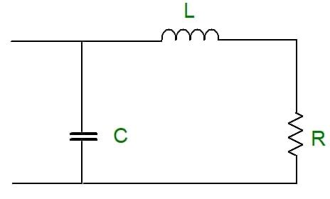
L-Network Matching
One common zero resistance matching network is the L-network. It consists of two reactive components, either a capacitor and an inductor or two capacitors or two inductors, connected in an L-shaped configuration.
The L-network can match a wide range of impedances by adjusting the values of the reactive components. The choice of components depends on the desired impedance transformation and the frequency range of operation.
For example, consider an L-network with a capacitor (C) and an inductor (L) used to match a source impedance (ZS) to a load impedance (ZL) at a specific frequency (f).
The values of C and L can be calculated using the following equations:
Q = √((ZL/ZS) – 1)
C = 1 / (2πfQZL)
L = QZS / (2πf)
where Q is the quality factor of the network.
By selecting the appropriate values for C and L, the L-network can provide impedance matching without resistive losses.
Pi-Network Matching
Another zero resistance matching network is the Pi-network. It consists of three reactive components, typically two capacitors and an inductor, arranged in a pi-shaped configuration.
The Pi-network offers more flexibility in impedance matching compared to the L-network. It can match a wider range of impedances and provides additional degrees of freedom in component selection.
The values of the components in a Pi-network can be calculated based on the desired impedance transformation and the operating frequency. The equations for a Pi-network with two capacitors (C1 and C2) and an inductor (L) are:
Q = √((ZL/ZS) – 1)
C1 = 1 / (2πfQZS)
C2 = 1 / (2πfQZL)
L = Q / (2πf√(ZSZL))
By properly designing the Pi-network, impedance matching can be achieved without resistive losses.
Transmission Line Matching
Transmission line matching is another technique for zero resistance impedance matching. It involves using a quarter-wavelength (λ/4) transmission line with a specific characteristic impedance to transform the load impedance to the desired value.
The characteristic impedance of the quarter-wavelength transmission line (Z0) is chosen to be the geometric mean of the source impedance (ZS) and the load impedance (ZL):
Z0 = √(ZSZL)
By using a quarter-wavelength transmission line with the appropriate characteristic impedance, the load impedance can be transformed to match the source impedance without resistive losses.
Transmission line matching is commonly used in RF and microwave circuits, where the wavelength of the signal is comparable to the physical dimensions of the PCB traces.

PCB Layout Techniques for Zero Resistance Matching
When implementing zero resistance matching networks on a PCB, proper layout techniques are essential to maintain the desired impedance and minimize parasitic effects. Some key considerations include:
- Component Placement:
- Place matching network components as close to the load or source as possible to minimize trace lengths and parasitic inductance.
-
Orient components to minimize coupling and crosstalk.
-
Trace Geometry:
- Use controlled impedance traces, such as microstrip or stripline, for the matching network.
- Maintain consistent trace width and spacing to ensure uniform impedance.
-
Avoid sharp bends or discontinuities in the traces to minimize reflections.
-
Grounding and Shielding:
- Provide a solid ground plane beneath the matching network to minimize ground inductance and provide a stable reference.
- Use ground vias near the components to provide low-impedance paths to the ground plane.
-
Consider shielding sensitive matching networks to reduce electromagnetic interference (EMI) and crosstalk.
-
Simulation and Verification:
- Perform electromagnetic (EM) simulations of the PCB layout to verify the impedance matching and identify any potential issues.
- Use time-domain reflectometry (TDR) or vector network analyzer (VNA) measurements to validate the impedance matching on the fabricated PCB.
By following these layout techniques and carefully designing the PCB, zero resistance matching networks can be effectively implemented, ensuring optimal impedance matching and signal integrity.

Frequently Asked Questions (FAQ)
- What is the purpose of impedance matching in PCB design?
-
Impedance matching ensures maximum power transfer, minimizes signal reflections, and maintains signal integrity in PCB circuits. It is particularly important for high-speed signals, RF circuits, and transmission lines.
-
What are the common methods for impedance matching in PCB design?
-
Common methods for impedance matching in PCB design include series termination, parallel termination, AC termination, stub matching, and transmission line matching. The choice of method depends on the specific circuit requirements and constraints.
-
What is zero resistance impedance matching?
-
Zero resistance impedance matching is a technique that uses purely reactive components, such as capacitors and inductors, to achieve impedance matching without resistive losses. It eliminates power dissipation in the matching network, improving efficiency and reducing heat generation.
-
What are the advantages of using zero resistance matching networks?
-
Zero resistance matching networks offer several advantages, including:
- Elimination of resistive losses, resulting in improved power efficiency.
- Reduced heat generation, which is beneficial for temperature-sensitive circuits.
- Increased flexibility in impedance matching, as reactive components can be easily tuned or adjusted.
- Compatibility with a wide range of frequencies and impedances.
-
What are the key considerations when designing zero resistance matching networks on a PCB?
- When designing zero resistance matching networks on a PCB, key considerations include:
- Proper component placement to minimize parasitic effects and trace lengths.
- Consistent trace geometry and controlled impedance for optimal signal propagation.
- Solid grounding and shielding to minimize ground inductance and reduce electromagnetic interference.
- Simulation and verification to validate the impedance matching and identify any potential issues.
By understanding the principles of impedance matching, utilizing zero resistance matching techniques, and following PCB layout best practices, designers can achieve optimal signal integrity, power transfer, and overall performance in their PCB designs.
Conclusion
Impedance matching is a critical aspect of PCB design, particularly for high-speed and RF circuits. By properly matching impedances, signal reflections can be minimized, power transfer can be optimized, and signal integrity can be maintained. Zero resistance impedance matching techniques, such as L-networks, Pi-networks, and transmission line matching, provide a means to achieve impedance matching without resistive losses.
When designing PCBs for impedance matching, careful consideration must be given to factors such as characteristic impedance, transmission line termination, stub matching, and component placement and routing. By following best practices and utilizing appropriate layout techniques, designers can effectively implement zero resistance matching networks on their PCBs.
As the demand for high-speed and high-frequency electronics continues to grow, the importance of impedance matching in PCB design will only increase. By understanding the principles and techniques discussed in this article, designers can tackle the challenges of impedance matching and create robust, high-performance PCBs that meet the stringent requirements of modern electronic systems.


Leave a Reply