Introduction to the ATmega32U4 breakout Board
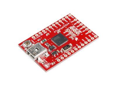
The ATmega32U4 breakout board is a versatile and powerful microcontroller development board that offers a wide range of features and capabilities for embedded systems projects. This breakout board is designed around the ATmega32U4 microcontroller, which is a popular choice among hobbyists, students, and professionals alike due to its robust performance, low power consumption, and extensive peripheral set.
Key Features of the ATmega32U4 Breakout Board
| Feature | Description |
|---|---|
| Microcontroller | ATmega32U4 (32KB Flash, 2.5KB SRAM, 1KB EEPROM) |
| Clock Speed | 16 MHz |
| USB Interface | USB 2.0 Full Speed (12 Mbps) |
| Digital I/O Pins | 26 |
| PWM Channels | 7 |
| Analog Input Channels | 12 |
| Operating Voltage | 5V |
| Dimensions | 2.7″ x 2.1″ (68.6mm x 53.3mm) |
The ATmega32U4 breakout board comes fully assembled and ready to use, making it an ideal choice for those who want to dive straight into their projects without the need for additional soldering or assembly. The board features a compact form factor, measuring just 2.7″ x 2.1″ (68.6mm x 53.3mm), which makes it suitable for use in space-constrained applications.
ATmega32U4 Microcontroller Overview
At the heart of the ATmega32U4 breakout board is the ATmega32U4 microcontroller, a powerful 8-bit AVR microcontroller manufactured by Microchip Technology (formerly Atmel). This microcontroller offers a rich set of features and capabilities, making it well-suited for a wide range of embedded systems applications.
ATmega32U4 Microcontroller Specifications
| Specification | Value |
|---|---|
| Flash Memory | 32KB |
| SRAM | 2.5KB |
| EEPROM | 1KB |
| Operating Voltage | 2.7V to 5.5V |
| CPU Speed | Up to 16 MHz |
| Hardware Multiplier | Yes |
| UART | 1 |
| SPI | 1 |
| I2C | 1 |
| USB | 2.0 Full Speed (12 Mbps) |
| Analog Comparator | 1 |
| 10-bit ADC Channels | 12 |
| 8-bit PWM Channels | 7 |
| External Interrupts | 8 |
The ATmega32U4 microcontroller boasts an impressive 32KB of flash memory for storing program code, 2.5KB of SRAM for data storage, and 1KB of EEPROM for non-volatile data storage. The microcontroller can operate at speeds up to 16 MHz and supports a wide operating voltage range from 2.7V to 5.5V, making it suitable for both low-power and high-performance applications.
One of the standout features of the ATmega32U4 is its built-in USB 2.0 Full Speed (12 Mbps) interface, which allows the microcontroller to communicate directly with a computer or other USB host devices without the need for an external USB-to-serial converter. This feature greatly simplifies the process of programming and debugging the microcontroller, as well as enabling the creation of USB-based projects such as custom keyboards, mice, and game controllers.

ATmega32U4 Breakout Board Pinout and Peripherals
The ATmega32U4 breakout board provides easy access to the microcontroller’s various input/output pins and peripherals through a set of clearly labeled headers. This section will explore the pinout of the breakout board and discuss some of the key peripherals available.
ATmega32U4 Breakout Board Pinout
| Pin | Function | Pin | Function |
|---|---|---|---|
| VCC | Power supply (5V) | GND | Ground |
| RST | Reset | AREF | Analog reference |
| D0 | Digital I/O pin 0 | D1 | Digital I/O pin 1 |
| D2 | Digital I/O pin 2 | D3 | Digital I/O pin 3 (PWM) |
| D4 | Digital I/O pin 4 | D5 | Digital I/O pin 5 (PWM) |
| D6 | Digital I/O pin 6 (PWM) | D7 | Digital I/O pin 7 |
| D8 | Digital I/O pin 8 | D9 | Digital I/O pin 9 (PWM) |
| D10 | Digital I/O pin 10 (PWM) | D11 | Digital I/O pin 11 (PWM) |
| D12 | Digital I/O pin 12 | D13 | Digital I/O pin 13 (PWM) |
| A0 | Analog input 0 | A1 | Analog input 1 |
| A2 | Analog input 2 | A3 | Analog input 3 |
| A4 | Analog input 4 (SDA) | A5 | Analog input 5 (SCL) |
The breakout board provides access to all 26 digital I/O pins of the ATmega32U4 microcontroller, with 7 of these pins capable of Pulse-Width Modulation (PWM) output for generating analog-like signals. Additionally, the board offers 12 analog input channels (A0-A11) for measuring external analog voltages.
USB Interface
The ATmega32U4 breakout board features a micro-USB connector that allows the microcontroller to communicate directly with a computer or other USB host devices. This USB interface can be used for programming the microcontroller, debugging, and data transfer. The ATmega32U4’s built-in USB capabilities enable it to emulate various USB devices, such as keyboards, mice, and serial ports, making it an excellent choice for projects that require USB connectivity.
Serial Communication
The breakout board supports several serial Communication Protocols, including UART, SPI, and I2C. These protocols allow the ATmega32U4 to communicate with external devices such as sensors, displays, and other microcontrollers.
- UART: The ATmega32U4 has one hardware UART that can be used for asynchronous serial communication with devices such as GPS modules, Bluetooth modules, or other microcontrollers.
- SPI: The Serial Peripheral Interface (SPI) is a synchronous serial communication protocol that enables high-speed data transfer between the ATmega32U4 and external devices such as SD cards, displays, or wireless communication modules.
- I2C: The Inter-Integrated Circuit (I2C) protocol is a two-wire synchronous serial communication protocol that allows the ATmega32U4 to communicate with a wide range of I2C-compatible devices, such as Temperature Sensors, real-time clocks, and EEPROM chips.
Analog-to-Digital Converter (ADC)
The ATmega32U4 breakout board provides access to the microcontroller’s 12 analog input channels, each with a 10-bit resolution. These analog inputs can be used to measure external analog voltages, such as those from sensors or potentiometers, and convert them into digital values for processing by the microcontroller.
Pulse-Width Modulation (PWM)
The breakout board offers 7 PWM-capable digital I/O pins, which can be used to generate analog-like signals for controlling the brightness of LEDs, the speed of motors, or the position of servos. PWM is a technique that involves rapidly toggling a digital output pin between high and low states, with the ratio of high to low time determining the average voltage output.

Programming the ATmega32U4 Breakout Board
The ATmega32U4 breakout board can be programmed using a variety of development environments and programming languages, making it accessible to users with different skill levels and preferences. This section will discuss some of the most popular options for programming the breakout board.
Arduino IDE
The Arduino Integrated Development Environment (IDE) is one of the most popular choices for programming the ATmega32U4 breakout board. The Arduino IDE is a cross-platform application that provides a simple, intuitive interface for writing, compiling, and uploading code to the microcontroller.
To program the ATmega32U4 breakout board using the Arduino IDE, follow these steps:
- Install the Arduino IDE on your computer by downloading it from the official Arduino website (https://www.arduino.cc/en/software).
- Connect the ATmega32U4 breakout board to your computer using a micro-USB cable.
- Open the Arduino IDE and select “Tools” > “Board” > “Arduino Leonardo” (or “Micro” if using a SparkFun Pro Micro).
- Select the appropriate serial port under “Tools” > “Port”.
- Write your code in the Arduino IDE using the C++ based Arduino programming language.
- Click the “Upload” button to compile and upload your code to the ATmega32U4 breakout board.
The Arduino IDE comes with a wide range of built-in libraries that simplify the process of interacting with various sensors, displays, and other peripherals. Additionally, there is a vast community of Arduino users who share their projects, libraries, and code examples online, making it easy to find resources and support when working on your own projects.
Atmel Studio
For users who prefer a more advanced development environment, Atmel Studio is a powerful IDE provided by Microchip Technology (formerly Atmel) for programming AVR and SAM microcontrollers, including the ATmega32U4. Atmel Studio offers a comprehensive set of tools for coding, debugging, and optimizing your embedded systems projects.
To program the ATmega32U4 breakout board using Atmel Studio, follow these steps:
- Install Atmel Studio on your computer by downloading it from the Microchip website (https://www.microchip.com/mplab/avr-support/atmel-studio-7).
- Connect the ATmega32U4 breakout board to your computer using a micro-USB cable.
- Create a new project in Atmel Studio by selecting “File” > “New” > “Project” and choosing “GCC C++ Executable Project”.
- Configure your project settings, such as the device (ATmega32U4), clock frequency, and programming interface (USB).
- Write your code in Atmel Studio using the C++ programming language.
- Build your project by clicking “Build” > “Build Solution”.
- Upload your code to the ATmega32U4 breakout board by clicking “Debug” > “Start Without Debugging”.
Atmel Studio provides advanced features such as code completion, syntax highlighting, and integrated debugging, making it a powerful tool for developing complex embedded systems projects.
Other Programming Options
In addition to the Arduino IDE and Atmel Studio, there are several other programming options available for the ATmega32U4 breakout board, including:
- PlatformIO: An open-source ecosystem for embedded development that supports multiple frameworks, including Arduino, and provides a unified IDE for programming various microcontrollers.
- AVR-GCC: A command-line toolchain for compiling and uploading code to AVR microcontrollers, including the ATmega32U4, using the C++ programming language.
- AVRDUDE: A command-line utility for programming AVR microcontrollers, which can be used in conjunction with AVR-GCC or other programming environments.
Regardless of your chosen programming environment, the ATmega32U4 breakout board offers a versatile and powerful platform for learning about embedded systems, prototyping ideas, and developing custom projects.

Example Projects Using the ATmega32U4 Breakout Board
To help you get started with the ATmega32U4 breakout board, this section will provide a few example projects that demonstrate some of the board’s capabilities.
Project 1: Blinking LED
This simple project will guide you through the process of blinking an LED connected to one of the ATmega32U4’s digital I/O pins using the Arduino IDE.
Materials needed:
– ATmega32U4 breakout board
– Micro-USB cable
– LED
– 220Ω resistor
– Breadboard
– Jumper wires
Steps:
1. Connect the ATmega32U4 breakout board to your computer using the micro-USB cable.
2. Place the LED and 220Ω resistor on the breadboard.
3. Connect the cathode (shorter leg) of the LED to the resistor and the other end of the resistor to GND on the breakout board.
4. Connect the anode (longer leg) of the LED to digital pin 13 on the breakout board.
5. Open the Arduino IDE and select “Tools” > “Board” > “Arduino Leonardo”.
6. Select the appropriate serial port under “Tools” > “Port”.
7. Copy the following code into a new sketch:
void setup() {
  pinMode(13, OUTPUT);
}

void loop() {
  digitalWrite(13, HIGH);
  delay(1000);
  digitalWrite(13, LOW);
  delay(1000);
}
- Click the “Upload” button to compile and upload the code to the ATmega32U4 breakout board.
- The LED should now blink on and off at a rate of once per second.
This simple project demonstrates how to use the Arduino IDE to control the digital I/O pins of the ATmega32U4 breakout board. You can modify the code to change the blink rate or connect additional LEDs to other digital pins to create more complex patterns.
Project 2: Analog Temperature Sensor
This project will demonstrate how to use the ATmega32U4’s analog input to read the temperature from a TMP36 analog temperature sensor and display the value in the Arduino IDE’s Serial Monitor.
Materials needed:
– ATmega32U4 breakout board
– Micro-USB cable
– TMP36 analog temperature sensor
– Breadboard
– Jumper wires
Steps:
1. Connect the ATmega32U4 breakout board to your computer using the micro-USB cable.
2. Place the TMP36 analog temperature sensor on the breadboard.
3. Connect the TMP36’s VCC pin to the 5V pin on the breakout board, the GND pin to the GND pin on the breakout board, and the VOUT pin to analog input A0 on the breakout board.
4. Open the Arduino IDE and select “Tools” > “Board” > “Arduino Leonardo”.
5. Select the appropriate serial port under “Tools” > “Port”.
6. Copy the following code into a new sketch:
const int TMP36_PIN = A0;

void setup() {
  Serial.begin(9600);
}

void loop() {
  int sensorValue = analogRead(TMP36_PIN);
  float voltage = sensorValue * 5.0 / 1024.0;
  float temperature = (voltage - 0.5) * 100;

  Serial.print("Temperature: ");
  Serial.print(temperature);
  Serial.println("°C");

  delay(1000);
}
- Click the “Upload” button to compile and upload the code to the ATmega32U4 breakout board.
- Open the Serial Monitor by clicking “Tools” > “Serial Monitor”.
- The temperature reading from the TMP36 sensor should now be displayed in the Serial Monitor, updating every second.
This project showcases how to use the ATmega32U4’s analog input to read data from an external sensor and display it in the Arduino IDE’s Serial Monitor. You can expand upon this project by adding additional sensors, creating a custom display, or logging the data to an external storage device.
Project 3: USB Keyboard
One of the unique features of the ATmega32U4 microcontroller is its built-in USB capabilities, which allow it to emulate various USB devices, such as keyboards. This project will demonstrate how to use the ATmega32U4 breakout board to create a simple USB keyboard that types a predefined message when a button is pressed.
Materials needed:
– ATmega32U4 breakout board
– Micro-USB cable
– Pushbutton
– 10kΩ resistor
– Breadboard
– Jumper wires
Steps:
1. Connect the ATmega32U4 breakout board to your computer using the micro-USB cable.
2. Place the pushbutton and 10kΩ resistor on the breadboard.
3. Connect one leg of the pushbutton to digital pin 2 on the breakout board and the other leg to one end of the 10kΩ resistor.
4. Connect the other end of the 10kΩ resistor to GND on the breakout board.
5. Open


Leave a Reply