Introduction to SMT Components
SMT components are electronic components designed to be mounted directly onto the surface of a printed circuit board (PCB). Unlike through-hole components, SMT components do not require leads to pass through holes in the PCB. This allows for smaller component sizes, increased component density, and automated assembly processes.
SMT components come in a wide variety of package types, each with its own set of dimensions, lead configurations, and thermal characteristics. Understanding these package types is crucial for designers and engineers to select the most suitable components for their specific applications.
Common SMT Component Package Types
1. Chip Components
Chip components are the simplest and most compact SMT package type. They are small, rectangular components with metallized end caps that serve as the connection points to the PCB. Chip components are commonly used for passive devices such as resistors, capacitors, and inductors.
| Package | Dimensions (mm) | Description |
|---|---|---|
| 0201 | 0.6 x 0.3 | Ultra-small chip component |
| 0402 | 1.0 x 0.5 | Small chip component |
| 0603 | 1.6 x 0.8 | Standard chip component |
| 0805 | 2.0 x 1.25 | Larger chip component |
| 1206 | 3.2 x 1.6 | Large chip component |
2. Small Outline Packages (SOP)
Small Outline Packages (SOP) are rectangular packages with leads extending from two sides of the component body. SOPs are commonly used for integrated circuits (ICs) such as operational amplifiers, Voltage Regulators, and logic devices.
| Package | Pitch (mm) | Description |
|---|---|---|
| SSOP | 0.65 | Shrink Small Outline Package |
| TSOP | 0.5 | Thin Small Outline Package |
| TSSOP | 0.65 | Thin Shrink Small Outline Package |
| QSOP | 0.635 | Quarter-size Small Outline Package |
3. Quad Flat Packages (QFP)
Quad Flat Packages (QFP) are square or rectangular packages with leads extending from all four sides of the component body. QFPs offer a higher pin count than SOPs and are suitable for more complex ICs such as microcontrollers and digital signal processors.
| Package | Pitch (mm) | Description |
|---|---|---|
| LQFP | 0.5, 0.4 | Low-profile Quad Flat Package |
| TQFP | 0.8, 0.65, 0.5 | Thin Quad Flat Package |
| PQFP | 0.8, 0.65, 0.5 | Plastic Quad Flat Package |
| CQFP | 0.5, 0.4 | Ceramic Quad Flat Package |
4. Ball Grid Array (BGA)
Ball Grid Array (BGA) packages have a grid of solder balls on the underside of the component body, allowing for a high pin count in a compact footprint. BGAs are used for complex ICs that require a large number of interconnections, such as processors, FPGAs, and ASICs.
| Package | Pitch (mm) | Description |
|---|---|---|
| PBGA | 1.27, 1.0, 0.8 | Plastic Ball Grid Array |
| CBGA | 1.27, 1.0, 0.8 | Ceramic Ball Grid Array |
| FBGA | 1.27, 1.0, 0.8 | Fine-pitch Ball Grid Array |
| LFBGA | 0.8, 0.65, 0.5 | Low-profile Fine-pitch Ball Grid Array |
5. Chip Scale Packages (CSP)
Chip Scale Packages (CSP) are miniaturized packages that have dimensions close to the size of the semiconductor die itself. CSPs offer a high level of integration and are commonly used in space-constrained applications such as mobile devices and wearables.
| Package | Description |
|---|---|
| WLCSP | Wafer-Level Chip Scale Package |
| FCCSP | Flip Chip Chip Scale Package |
| FBGA-CSP | Fine-pitch Ball Grid Array Chip Scale Package |

SMT Component Selection Considerations
When selecting SMT components for a design, engineers must consider several factors to ensure optimal performance, reliability, and manufacturability.
1. Footprint Compatibility
The component footprint must be compatible with the PCB layout and the assembly process. Designers should adhere to the recommended land pattern dimensions and spacing guidelines provided by the component manufacturer.
2. Thermal Characteristics
SMT components generate heat during operation, which must be dissipated to prevent thermal damage. The package type and size influence the component’s thermal characteristics. Larger packages generally have better heat dissipation capabilities compared to smaller ones.
3. Electrical Characteristics
The electrical characteristics of the SMT component must meet the requirements of the circuit design. This includes parameters such as power rating, voltage rating, tolerance, and frequency response.
4. Reliability and Quality
Component reliability and quality are critical factors in ensuring the long-term performance of the electronic device. Designers should select components from reputable manufacturers and consider factors such as moisture sensitivity level (MSL), thermal cycling performance, and electrostatic discharge (ESD) protection.
5. Cost and Availability
Cost and availability are important considerations in component selection. Designers should strike a balance between component performance and cost while ensuring a reliable supply chain.

SMT Assembly Process Overview
The SMT assembly process involves several key steps to mount components onto the PCB surface.
1. Solder paste printing
Solder paste, a mixture of tiny solder particles and flux, is applied to the PCB pads using a stencil printing process. The stencil ensures precise deposition of the solder paste onto the desired locations.
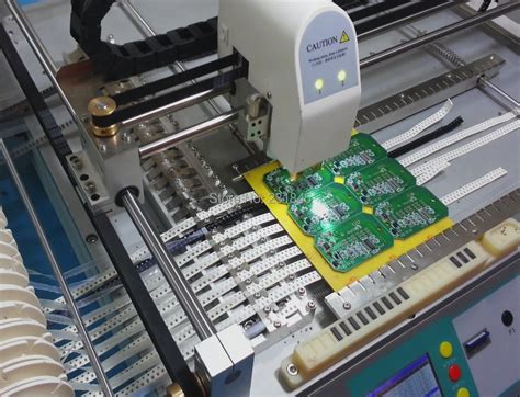
2. Component Placement
SMT components are picked and placed onto the solder paste-coated pads using automated Pick-and-place machines. These machines use vacuum nozzles or grippers to accurately position the components based on the PCB layout data.
3. Reflow Soldering
The PCB with placed components undergoes a reflow soldering process in a reflow oven. The assembly is subjected to a controlled temperature profile, causing the solder paste to melt and form a strong mechanical and electrical bond between the component leads and the PCB pads.
4. Inspection and Testing
After the reflow soldering process, the assembled PCB undergoes visual inspection and automated optical inspection (AOI) to detect any defects or misaligned components. Electrical testing, such as in-circuit testing (ICT) or Functional Testing, is performed to verify the proper functioning of the assembled board.

Frequently Asked Questions (FAQ)
1. What is the difference between SMT and through-hole technology?
SMT components are mounted directly onto the surface of the PCB, while through-hole components have leads that are inserted into holes drilled in the PCB and soldered on the opposite side. SMT allows for smaller component sizes, higher component density, and automated assembly processes compared to through-hole technology.
2. What are the advantages of using SMT components?
SMT components offer several advantages, including:
– Smaller component sizes, enabling miniaturization of electronic devices
– Higher component density, allowing for more compact and lightweight designs
– Automated assembly processes, reducing manufacturing time and costs
– Improved mechanical and thermal performance due to direct surface mounting
– Enhanced high-frequency performance due to shorter lead lengths
3. How do I select the appropriate SMT component package for my design?
When selecting an SMT component package, consider factors such as:
– Footprint compatibility with the PCB layout and assembly process
– Thermal characteristics and heat dissipation requirements
– Electrical characteristics and performance requirements
– Reliability and quality standards
– Cost and availability constraints
4. What is the purpose of solder paste in the SMT assembly process?
Solder paste serves two primary purposes in the SMT assembly process. First, it provides a temporary adhesive to hold the components in place during the placement process. Second, it contains the solder material that forms the electrical and mechanical connection between the component leads and the PCB pads during the reflow soldering process.
5. How can I ensure the reliability of my SMT assembly?
To ensure the reliability of your SMT assembly, consider the following practices:
– Select high-quality components from reputable manufacturers
– Follow recommended land pattern dimensions and spacing guidelines
– Use appropriate solder paste and stencil thickness for the specific component package
– Implement a robust reflow soldering profile with proper temperature control
– Conduct thorough inspection and testing to identify and address any defects or issues
Conclusion
SMT components are the backbone of modern electronic assemblies, offering numerous advantages in terms of size, performance, and manufacturing efficiency. Understanding the various SMT component package types and their characteristics is essential for designers and engineers to make informed decisions during the component selection and PCB design process.
By considering factors such as footprint compatibility, thermal characteristics, electrical performance, reliability, and cost, designers can optimize their SMT assemblies for specific applications. The SMT assembly process, involving solder paste printing, component placement, reflow soldering, and inspection, ensures the accurate and reliable mounting of SMT components onto the PCB surface.
As electronic devices continue to evolve and demand for miniaturization and functionality grows, SMT components will remain a crucial element in the electronics industry. Staying updated with the latest advancements in SMT packaging technologies and assembly processes will enable engineers to design and manufacture cutting-edge electronic products that meet the ever-changing needs of the market.


Leave a Reply