Introduction to 556 Circuits
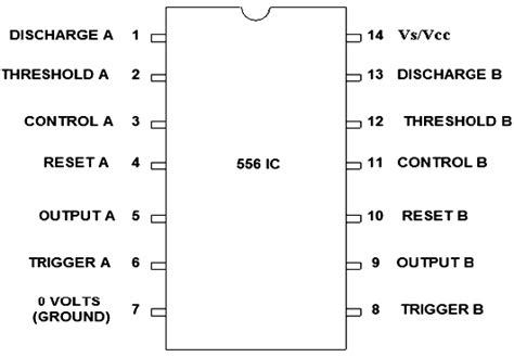
The 556 integrated circuit (IC) is a dual version of the popular 555 timer IC. It contains two independent 555 timers in a single 14-pin package, allowing for more complex timing and control applications. The 556 is widely used in various electronic projects, from simple blinking LEDs to advanced PWM motor control and sequencing circuits.
Key Features of 556 Circuits
- Dual 555 timers in a single package
- Wide supply voltage range (4.5V to 18V)
- Adjustable duty cycle (from 50% to nearly 100%)
- Low power consumption
- Capable of generating precise time delays and oscillation
- Compatible with bipolar and CMOS logic families
How 556 Circuits Work
Each of the two 555 timers in a 556 IC has three operating modes: astable, monostable, and bistable. The mode is determined by the connections made to the control pins of the IC.
Astable Mode
In astable mode, the 556 operates as a free-running oscillator, continuously generating a square wave output. The frequency and duty cycle of the output are determined by the values of the external resistors and capacitor connected to the IC.
Astable Mode Pin Configuration
| Pin | Function |
|---|---|
| GND | Ground |
| TRIG | Trigger input |
| OUT | Output |
| RESET | Reset input |
| CTRL | Control voltage input |
| THR | Threshold input |
| DIS | Discharge pin |
| VCC | Positive supply voltage |
Astable Mode Frequency Formula
The frequency of the output square wave in astable mode can be calculated using the following formula:
f = 1.44 / ((R1 + 2 * R2) * C)
Where:
– f is the frequency in Hz
– R1 and R2 are the values of the external resistors in ohms
– C is the value of the external capacitor in farads
Monostable Mode
In monostable mode, also known as one-shot mode, the 556 generates a single output pulse of a predetermined duration when triggered by an input pulse. The pulse duration is determined by the values of the external resistor and capacitor connected to the IC.
Monostable Mode Pin Configuration
| Pin | Function |
|---|---|
| GND | Ground |
| TRIG | Trigger input |
| OUT | Output |
| RESET | Reset input |
| CTRL | Control voltage input |
| THR | Threshold input |
| DIS | Discharge pin |
| VCC | Positive supply voltage |
Monostable Mode Pulse Duration Formula
The pulse duration in monostable mode can be calculated using the following formula:
t = 1.1 * R * C
Where:
– t is the pulse duration in seconds
– R is the value of the external resistor in ohms
– C is the value of the external capacitor in farads
Bistable Mode
In bistable mode, also known as flip-flop mode, the 556 acts as a basic SR (set-reset) flip-flop. The output can be set or reset by applying appropriate logic levels to the trigger and reset inputs.
Bistable Mode Pin Configuration
| Pin | Function |
|---|---|
| GND | Ground |
| TRIG | Set input |
| OUT | Output |
| RESET | Reset input |
| CTRL | Control voltage input |
| THR | Connected to TRIG |
| DIS | Not used |
| VCC | Positive supply voltage |

Applications of 556 Circuits
556 circuits find applications in a wide range of electronic projects, some of which are listed below:
- LED flashers and sequencers
- Pulse Width Modulation (PWM) motor control
- Timers and delay circuits
- Alarm systems
- Sound effects generators
- Frequency dividers
- Voltage-controlled oscillators (VCOs)
- Capacitance meters
LED Flasher Circuit
A simple LED flasher circuit can be built using a 556 IC in astable mode. The circuit diagram and component values are shown below:
| Component | Value |
|---|---|
| R1 | 1 kΩ |
| R2 | 10 kΩ |
| C1 | 10 μF |
| LED1, LED2 | Any color |
In this circuit, the two 555 timers in the 556 IC are configured in astable mode, with their outputs driving two LEDs. The flashing rate can be adjusted by changing the values of R1, R2, and C1.
PWM Motor Control Circuit
A 556 IC can be used to generate PWM signals for controlling the speed of DC motors. The circuit diagram and component values are shown below:
| Component | Value |
|---|---|
| R1 | 1 kΩ |
| R2 | 10 kΩ potentiometer |
| C1 | 0.1 μF |
| Q1 | TIP120 NPN Darlington transistor |
| D1 | 1N4001 diode |
| Motor | DC motor (voltage rating depends on supply voltage) |
In this circuit, one of the 555 timers in the 556 IC is configured in astable mode to generate a PWM signal. The duty cycle of the PWM signal is adjusted using the potentiometer R2, which in turn controls the speed of the DC motor. The Darlington transistor Q1 acts as a switch to drive the motor, while the diode D1 protects the transistor from back EMF generated by the motor.

Troubleshooting 556 Circuits
When working with 556 circuits, you may encounter issues such as incorrect output, unstable operation, or no output at all. Here are some common problems and their solutions:
-
No output: Check the power supply connections and ensure that the IC is receiving the correct voltage. Also, verify that the control pins are connected correctly according to the desired operating mode.
-
Incorrect output frequency or pulse duration: Double-check the values of the external resistors and capacitors and ensure they are connected to the correct pins. Use the appropriate formulas to calculate the desired frequency or pulse duration.
-
Unstable operation: Make sure that the power supply is clean and stable. Use decoupling capacitors (0.1 μF ceramic) between the VCC and GND pins of the IC to reduce noise. Also, ensure that the timing capacitors are of good quality and have low leakage.
-
Overheating: If the 556 IC is driving a high-current load, such as a motor or multiple LEDs, ensure that the maximum current rating of the IC (200 mA per timer) is not exceeded. Use a heat sink if necessary to dissipate excess heat.

FAQ
1. Can a 556 IC be used as a direct replacement for two 555 ICs?
Yes, a 556 IC can be used as a direct replacement for two 555 ICs in most cases. However, keep in mind that the pinout of the 556 is different from that of the 555, so the circuit connections must be modified accordingly.
2. What is the maximum supply voltage for a 556 IC?
The maximum supply voltage for a 556 IC is typically 18V. However, it is recommended to check the datasheet of the specific manufacturer for the exact value.
3. Can a 556 IC be used with a microcontroller?
Yes, a 556 IC can be used with a microcontroller in various ways. For example, the microcontroller can be used to control the operating mode of the 556 or to adjust the timing parameters dynamically.
4. How can I change the duty cycle of the output in astable mode?
To change the duty cycle of the output in astable mode, you need to adjust the values of the external resistors R1 and R2. The duty cycle can be calculated using the formula:
Duty Cycle = (R1 + R2) / (R1 + 2 * R2)
By varying the ratio of R1 and R2, you can achieve duty cycles ranging from 50% to nearly 100%.
5. What is the purpose of the control voltage pin (CTRL) in a 556 IC?
The control voltage pin (CTRL) in a 556 IC allows you to modulate the timing parameters of the IC using an external voltage. By applying a voltage to the CTRL pin, you can change the threshold and trigger levels, which in turn affects the frequency and duty cycle of the output. This feature is useful for creating voltage-controlled oscillators (VCOs) and other advanced applications.
Conclusion
The 556 IC is a versatile and widely used dual timer that finds applications in a wide range of electronic projects. By understanding its operating modes, pin configuration, and timing formulas, you can easily design and troubleshoot circuits that require precise timing and control. Whether you are a beginner or an experienced electronics enthusiast, the 556 IC is a valuable tool to have in your arsenal.


Leave a Reply