Introduction to Flasher Circuits
A flasher circuit is an electronic circuit that produces a repetitive on-off light or sound output. It is commonly used in various applications such as emergency lights, turn signals, and attention-grabbing displays. The basic principle behind a flasher circuit is to create an oscillating signal that alternately turns the output device (e.g., an LED or a buzzer) on and off at a desired frequency.
In this comprehensive article, we will dive deep into the world of flasher circuits. We will explore the different types of flasher circuits, their components, and how to design and build your own flasher circuit. Whether you are an electronics enthusiast, a hobbyist, or a professional, this article will provide you with all the information you need to create a flasher circuit from scratch.
Types of Flasher Circuits
There are several types of flasher circuits, each with its own characteristics and applications. Let’s take a look at some of the most common types:
Astable Multivibrator Flasher
An astable multivibrator is a circuit that generates a continuous stream of rectangular pulses. It consists of two transistors, resistors, and capacitors. The transistors alternately switch on and off, causing the LED or other output device to flash at a determined frequency. Astable multivibrators are widely used in applications such as blinking lights and simple oscillators.
555 Timer Flasher
The 555 timer is a versatile integrated circuit (IC) that can be configured to create various timing and oscillation functions. When used as a flasher, the 555 timer generates a square wave output that can drive an LED or other load. The flashing frequency can be easily adjusted by changing the values of the external resistors and capacitors connected to the 555 timer.
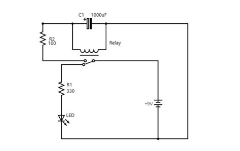
Relay Flasher
A relay flasher uses an electromechanical relay to switch the power on and off to the load. The relay is controlled by a timing circuit, which can be implemented using a 555 timer or other oscillator. Relay flashers are commonly used in automotive applications, such as turn signals and hazard lights, due to their ability to handle higher currents.
Microcontroller-Based Flasher
With the advent of microcontrollers, it is possible to create programmable flasher circuits. A microcontroller, such as an Arduino or PIC, can be programmed to generate the desired flashing patterns and control the output devices. Microcontroller-based flashers offer flexibility and can be easily customized to suit specific requirements.

Components of a Flasher Circuit
To build a flasher circuit, you will need several components. Let’s take a closer look at each of them:
Resistors
Resistors are passive components that limit the flow of electric current in a circuit. In a flasher circuit, resistors are used to control the current flowing through the LED or other load, as well as to set the flashing frequency in combination with capacitors.
Capacitors
Capacitors are components that store electrical energy and release it when required. In a flasher circuit, capacitors are used to create time delays and determine the flashing frequency. The charging and discharging of capacitors in conjunction with resistors create the oscillating behavior of the circuit.
Transistors
Transistors are semiconductor devices that can act as switches or amplifiers in electronic circuits. In a flasher circuit, transistors are used to switch the current on and off to the load. Bipolar junction transistors (BJTs) and metal-oxide-semiconductor field-effect transistors (MOSFETs) are commonly used in flasher circuits.
LEDs
Light-emitting diodes (LEDs) are semiconductor devices that emit light when an electric current passes through them. LEDs are often used as the output device in flasher circuits due to their low power consumption, long lifespan, and availability in various colors.
Integrated Circuits (ICs)
Integrated circuits are miniaturized electronic circuits that consist of multiple components, such as transistors, resistors, and capacitors, fabricated on a single semiconductor chip. ICs like the 555 timer are commonly used in flasher circuits to simplify the design and reduce the component count.

Designing a Flasher Circuit
Now that we have covered the types and components of flasher circuits, let’s dive into the process of designing your own flasher circuit.
Step 1: Define the Requirements
Before starting the design process, it is essential to define the requirements for your flasher circuit. Consider the following factors:
- Purpose of the flasher circuit (e.g., emergency light, turn signal, decoration)
- Desired flashing frequency or pattern
- Power supply requirements (e.g., battery voltage, current consumption)
- Output device specifications (e.g., LED type, current rating)
Step 2: Select the Flasher Circuit Type
Based on your requirements, select the appropriate type of flasher circuit. Consider factors such as simplicity, cost, and flexibility. For example, if you need a simple and low-cost solution, an astable multivibrator or 555 timer flasher might be suitable. If you require programmability and advanced features, a microcontroller-based flasher would be a better choice.
Step 3: Design the Circuit
Once you have selected the flasher circuit type, it’s time to design the actual circuit. This involves selecting the appropriate components and determining their values. Here are some general guidelines:
- Choose resistor values that limit the current through the LED or other load to a safe level.
- Select capacitor values that, in combination with the resistors, provide the desired flashing frequency.
- Ensure that the transistors or ICs used are capable of handling the required current and voltage levels.
- Use appropriate power supply decoupling capacitors to reduce noise and ensure stable operation.
You can use circuit simulation software, such as LTspice or Multisim, to design and simulate your flasher circuit before building it. This allows you to verify the circuit’s functionality and make any necessary adjustments.
Step 4: Build and Test the Circuit
After designing the circuit, it’s time to build and test it. Follow these steps:
- Gather all the necessary components and tools, such as a breadboard, jumper wires, soldering iron, and multimeter.
- Assemble the circuit on a breadboard or printed circuit board (PCB) according to your design.
- Double-check the component values and connections to ensure accuracy.
- Apply power to the circuit and observe the output. Use a multimeter to measure voltages and currents at various points in the circuit.
- Make any necessary adjustments or troubleshoot if the circuit does not work as expected.

Example Flasher Circuit
To illustrate the concepts discussed, let’s take a look at a simple 555 timer-based flasher circuit.
Circuit Diagram
        +9V
         |
        +-+
        | |
        | |  R1
        | |  4.7kΩ
        +-+
         |
         |     C1
         +-----||------+
         |     0.1µF   |
         |             |
         |             |
         |     +-------+-------+
         |     |       |       |
         +-----|RESET  |       |
               |       |       |
               |THRESH |       |
         +-----|       |       |
         |     |TRIG   |       |
         |     +-------+-------+
         |             |       |
         |             |       |
         |             |       |
         |             |       |
         |             |       |
   LED   |             |       |
         |             |       |
    /|   |             |       |
   /-+---+-------------+       |
        GND           OUTPUT  |
                              |
                              |
                              |
                             GND
Component Values
- R1: 4.7 kΩ resistor
- C1: 0.1 µF capacitor
- LED: Any standard LED
- 555 Timer IC
Explanation
In this circuit, the 555 timer is configured in astable mode. The resistor R1 and capacitor C1 determine the flashing frequency. The LED is connected to the output of the 555 timer and will flash at the determined frequency.
When power is applied, the capacitor C1 charges through R1 until the voltage at the THRESH pin reaches 2/3 of the supply voltage. At this point, the internal comparator triggers, and the output goes low, discharging C1 through the TRIG pin. When the voltage at the TRIG pin falls below 1/3 of the supply voltage, the output goes high again, and the cycle repeats.
The flashing frequency can be calculated using the following formula:
f = 1.44 / (R1 * C1)
With the given component values, the flashing frequency will be approximately 1.44 / (4.7 kΩ * 0.1 µF) ≈ 3 Hz, resulting in a flashing rate of about 3 times per second.
Troubleshooting Flasher Circuits
Despite careful design and assembly, flasher circuits may sometimes fail to work as expected. Here are some common issues and troubleshooting tips:
LED Not Flashing
- Check the power supply connections and ensure that the circuit is receiving the correct voltage.
- Verify that the LED is connected with the correct polarity (anode to the positive, cathode to the negative).
- Ensure that the current-limiting resistor is of the appropriate value to protect the LED.
- Check for any loose connections or damaged components.
Incorrect Flashing Frequency
- Double-check the values of the resistors and capacitors that determine the flashing frequency.
- Ensure that the components are connected correctly according to the circuit diagram.
- Use a multimeter to measure the actual values of the components and compare them with the intended values.
Erratic or Unstable Flashing
- Check for any noise sources nearby that could be interfering with the circuit, such as motors or switching power supplies.
- Add decoupling capacitors close to the power supply pins of ICs to reduce noise.
- Ensure that the circuit is properly grounded and that there are no ground loops.
Component Overheating
- Verify that the components, especially transistors and ICs, are operating within their rated specifications.
- Check for short circuits or excessive current draw that could cause components to overheat.
- Use heatsinks or other cooling methods if necessary to dissipate heat from components.
Applications of Flasher Circuits
Flasher circuits find applications in various fields, such as:
- Automotive: Turn signals, hazard lights, and brake lights in vehicles often use flasher circuits.
- Safety and Security: Emergency lights, warning beacons, and strobe lights in alarm systems and emergency vehicles.
- Advertising and Displays: Attention-grabbing displays, such as flashing signs and billboards.
- Toys and Gadgets: Flashing lights in toys, wearable electronics, and novelty items.
- Lighting and Decoration: Decorative lighting effects, such as flashing Christmas lights or party lights.
Frequently Asked Questions (FAQ)
1. Can I use a different LED color in the example flasher circuit?
Yes, you can use any standard LED color in the example circuit. Just make sure to select an appropriate current-limiting resistor value based on the LED’s forward voltage and current specifications.
2. How can I change the flashing frequency of the 555 timer flasher circuit?
To change the flashing frequency, you can modify the values of resistor R1 and capacitor C1. Increasing the resistance or capacitance will decrease the frequency, while decreasing the resistance or capacitance will increase the frequency. Use the formula f = 1.44 / (R1 * C1) to calculate the new frequency.
3. Can I power the flasher circuit using a battery?
Yes, you can power the flasher circuit using a battery. Make sure that the battery voltage is compatible with the circuit components, especially the LED and any ICs used. Also, consider the battery’s capacity and the circuit’s current consumption to determine the battery life.
4. How can I make the flasher circuit more energy-efficient?
To make the flasher circuit more energy-efficient, you can use low-power components such as LEDs with higher efficiency or low-power ICs. Additionally, you can optimize the flashing frequency and duty cycle to reduce power consumption. Using a microcontroller-based flasher allows for more precise control over power management.
5. Can I control the flasher circuit remotely?
Yes, you can control the flasher circuit remotely by integrating it with a wireless module, such as Bluetooth or Wi-Fi. This allows you to turn the flasher on and off or change its parameters using a remote control or a smartphone app. However, this requires additional components and programming.
Conclusion
Flasher circuits are versatile and widely used in various applications. By understanding the different types of flasher circuits, their components, and the design process, you can create your own flasher circuits tailored to your specific needs.
Remember to define your requirements, select the appropriate flasher circuit type, design the circuit carefully, and test it thoroughly. Don’t forget to consider factors such as power efficiency, reliability, and safety when designing your flasher circuit.
With the knowledge gained from this article, you are now equipped to explore the world of flasher circuits and create innovative projects. Whether you are building an attention-grabbing display, a safety device, or a fun gadget, the possibilities are endless.
So go ahead, grab your components, and start designing your own flasher circuit today!


Leave a Reply