Introduction
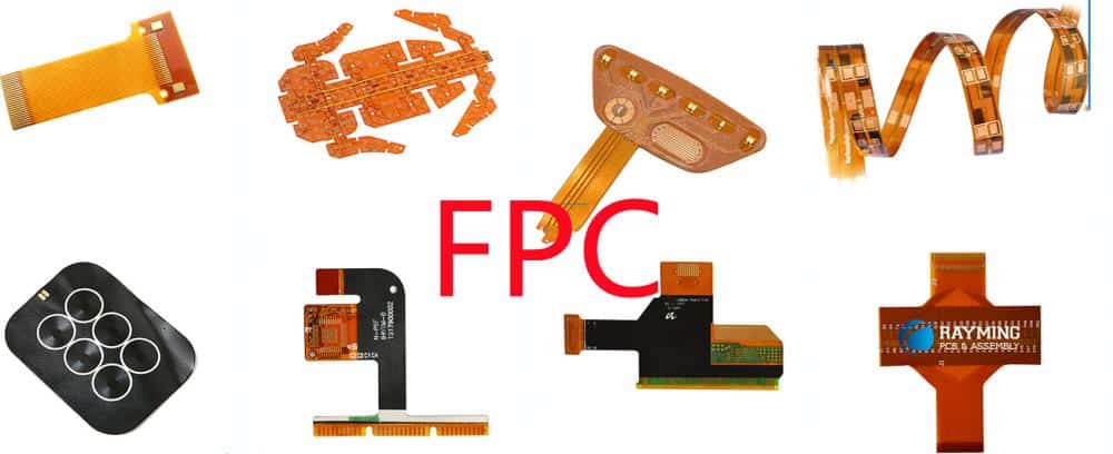
Flexible printed circuit boards (flex PCBs or flex circuits) are made from flexible insulating substrate materials that can bend and flex while still providing electrical connections. They allow printed circuits to be folded, twisted or formed to fit tightly within products with space and shape constraints. Flex PCBs are widely used in consumer electronics, medical devices, industrial equipment, automotive applications and more.
The substrate materials used in flex PCBs must be thin and flexible while still providing electrical insulation and heat resistance. Common substrate materials include polyimide, polyester, fluoropolymer and others. The conductive traces are typically made from rolled annealed copper foil that is laminated onto the substrate. The properties and benefits of different flex PCB substrate materials are discussed in this article.
Polyimide Film
Polyimide film is one of the most widely used flexible substrate materials for printed circuits. The thermoset polyimide material can withstand high temperatures (up to 300°C) and is known for its excellent chemical resistance. Polyimide films like Kapton from DuPont are commonly between 25 to 100 microns thick.
Some key properties and advantages of polyimide flex PCB substrates:
- High heat resistance and thermal stability
- Excellent chemical resistance
- Good dielectric strength and electrical insulation
- Flexible even at low thicknesses like 25 microns
- Withstands folding and flexing without damage
- Flame retardant with high resistance to burning
- Compatible with common PCB processing methods
Polyimide is more expensive than other flex substrate options but provides very good performance across a range of mechanical, electrical and thermal properties. It is commonly used in aerospace, automotive and industrial applications requiring robustness and reliability.
Polyimide Substrate Specifications
| Property | Value |
|---|---|
| Dielectric Constant | 3.4 – 3.6 at 1 MHz |
| Dielectric Strength | 15 kV/mm |
| Volume Resistivity | >10^16 ohm-cm |
| Water Absorption | <2.5% after 24 hr immersion |
| Operating Temperature | -269°C to +400°C |
Polyester Film
Polyester films like Mylar and Melinex are also commonly used as the insulating substrate for flex PCBs. Polyester films are thinner and more economical than polyimide. However, they have lower maximum temperature ratings around 150°C.
Key properties and benefits of polyester PCB substrates:
- Low moisture absorption
- Good chemical resistance
- High tensile strength and flexibility
- Cost effective compared to polyimide
- Stable electrical properties over frequency
- Withstands repeated flexing without fatigue
- Simple processing and lamination
Polyester films are often used when very thin and flexible substrates are needed for dynamic flexing applications. The lower cost makes polyester suitable for high volume consumer electronics. However, the lower heat resistance limits use in harsh environments.
Polyester Substrate Specifications
| Property | Value |
|---|---|
| Dielectric Constant | 3.2 – 3.3 at 1 MHz |
| Dielectric Strength | >600 V/mil |
| Volume Resistivity | >10^15 ohm-cm |
| Max Operating Temperature | 150°C |
| Melting Point | 255°C |
Fluoropolymer Films
Fluoropolymer films like PTFE (polytetrafluoroethylene) provide the highest heat resistance among common flex PCB substrate materials, withstanding temperatures exceeding 260°C in some cases. The fluoropolymer material also provides excellent chemical inertness and weather resistance. However, PTFE substrates have high material costs due to complex manufacturing.
Key properties of PTFE and fluoropolymer flex substrates:
- Extremely high heat resistance, withstanding over 260°C
- Chemically inert with universal chemical resistance
- Hydrophobic with very low moisture absorption
- Good electrical insulation properties
- Poor adhesion requires special treatments
- Relatively rigid compared to other flex substrates
- Expensive material costs
The unusual properties of fluoropolymers make them suitable for specialized high temperature or chemical resistant applications. The adhesion challenges can be overcome with proper surface treatments.
PTFE Substrate Specifications
| Property | Value |
|---|---|
| Dielectric Constant | 2.1 – 2.2 at 1 MHz |
| Dielectric Strength | 1 – 5 kV/mil |
| Volume Resistivity | >10^18 ohm-cm |
| Max Operating Temperature | 260°C |
| Melting Point | 327°C |
Liquid Crystal Polymer Films
Liquid crystal polymer (LCP) films provide an interesting alternative to conventional polyimide and polyester substrates. LCPs like the Vectra brand have very high heat resistance up to 250°C while remaining thin, flexible and easy to process. The oriented polymer structure also provides excellent electrical properties.
Advantages of LCP substrates:
- Heat resistance up to 250°C
- Thin films with excellent flexibility
- Low moisture absorption and high chemical resistance
- Stable dielectric properties
- Withstands flexing without fatigue or cracks
- Good dimensional stability
- Easily laminated using standard methods
The combination of properties allows LCP to replace polyimide in many high temperature flex PCB applications. LCP substrates are also well suited for the newest flex-rigid PCB designs. The main downside is the higher material cost due to more complex manufacturing.
Liquid Crystal Polymer Specifications
| Property | Value |
|---|---|
| Dielectric Constant | 3.2 – 3.5 at 1 MHz |
| Dielectric Strength | >600 V/mil |
| Volume Resistivity | >10^15 ohm-cm |
| Max Operating Temperature | 250°C |
| Glass Transition Temperature | >280°C |
Factors in Substrate Selection
With the variety of flexible PCB substrate materials available, the optimal choice depends on factors like:
- Operating Temperature Range – Maximum and minimum temperature rating.
- Flexibility and Thickness – How much bending is needed? Thinner films improve flex life.
- Chemical Exposure – Will the PCB contact solvents or other chemicals?
- Cost – Polyimide and LCP are more expensive than polyester.
- Dielectric Properties – Important for high frequency or RF applications.
- Adhesion – Some substrates require surface treatments.
- Production Volume – Longer rolls are more cost effective for high volume continuous production.
- Flammability – Some applications require flame retardant materials.
The substrate choice should be made based on which material provides the optimal balance of properties needed for the specific flex PCB application and operating conditions.
Conductor Materials
While the insulating substrate provides the foundation, the conductive traces and pads allow the transmission of power and signals. The conductors are typically made from rolled annealed copper foil laminated onto the substrate.
Rolled Copper Foil
Rolled copper foil provides an optimal balance of conductivity, flexibility, durability, and cost effectiveness for flex PCB fabrication. The foils are produced by rolling high purity copper to the desired thickness. Common weights (thicknesses) include:
- 1/4 oz (8.5 μm)
- 1/2 oz (17 μm)
- 1 oz (35 μm)
- 2 oz (70 μm)
The thinner foils allow tighter bendingradii while the thicker foils can carry more current. An anti-tarnish layer is often applied to prevent oxidation. The foil is bonded to the substrate using heat and adhesive.
Copper Plating
Copper can also be electroplated or electrolessly plated onto the PCB substrate to form the conductive traces and pads. Plating allows very thin copper thicknesses down to 5 microns while ensuring excellent adhesion. Fine line traces and spaces down to 6 microns can be achieved.
Plated copper has higher hardness and lower ductility than rolled foil. Annealing can help improve ductility and elongation for dynamic flexing applications.
Other Conductor Materials
Alternative conductor materials are sometimes used in challenging flex PCB applications:
- Silver – More conductive than copper but much higher cost. Used for high frequency or flexible antennas.
- Aluminum – Lower cost than copper but less conductive. Prone to oxidation.
- Carbon Nanotubes – Under development for transparent flex circuits.
PCB Lamination
Bonding the conductive copper traces to the insulating substrate is a critical step in flex PCB fabrication. Thermal lamination processes are used to adhere the layers using heat and adhesive.
The stacked material layers are subjected to high temperature and pressure in a lamination press. Typical parameters are 185°C at 200 PSI for 90 to 120 minutes. The adhesive layer softens and flows to bond the conductors to substrate.
Common adhesive materials include acrylic, phenolic butyral or epoxy. Modifications can improve adhesion to different substrates. Surface treatments like chemical etching may be used to improve bond strength.
Protective Coverlayers
Coverlayers and coatings are often applied to the top and bottom of flex circuits to provide protection from the environment. Common coverlayer materials include polyimide, polyester, epoxy, silicone, urethane and parylene.
Coverlayers provide:
- Moisture and leak protection
- Increased dielectric withstand voltage
- Physical and chemical protection
- Insulation between conductors
- Smoother surface for printing or marking
Flex PCB Design Guidelines
Proper design is critical for flex PCB reliability. Key guidelines include:
Bend radius
- Use large bend radii whenever possible
- Minimum bend radius depends on materials and layers
- Dynamic flexing needs larger bend radius
Conductor width and spacing
- Wide conductors withstand flexing better
- Increase spacing between conductors at fold points
Avoid 90° bends
- Use rounded corners instead of 90° bends
- 45° chamfers reduce stress
Avoid delamination
- Adhesive selection is critical
- Ensure proper pretreatments
- Anchors can help
Reinforcements
- Consider stiffeners at connector areas
- Carefully designed rigid sections
Applications of Flexible PCBs
The unique benefits of flex PCB technology make them well suited for many modern electronic products:
Wearable devices
- Flexible circuits conform to body and clothing
- Improved comfort and durability
Consumer electronics
- Allow folding and curving
- Save space with 3D assembly vs rigid boards
Medical devices
- Flexible circuits for implants, catheter, and instruments
- Can withstand repeated sterilization
Automotive
- Withstand vibration, shock, and flexing
- Foldable circuits for new concept cars
Robotics and UAVs
- Dynamic movement with flexing joints
- Lightweight compared to wires
Flex antennas
- Aerospace and telecom systems
- Can be wrapped around structures
Flexible displays
- Curved and rollable displays
- Bendable LCD and OLED panels
Flexible hybrid electronics (FHE)
- Merging thin-film electronics on plastic substrates
- Broad range of new applications
Pros and Cons of Flex Circuits
Pros
- Extremely flexible and dynamic
- Lightweight, thin, and compact
- 3D assembly and tight space routing
- Vibration and shock resistance
- High reliability with millions of flex cycles
- Eliminates rigid connectors and cables
- Lower assembly time and costs
Cons
- Limited current carrying capacity
- Can be more expensive than rigid PCBs
- Requires specialized design and fabrication
- Repair and rework is challenging
- Larger minimum bending radius than wires
Future Outlook
Flexible printed circuits will continue expanding as wearables, consumer devices, medical electronics, automotive, and many other applications seek to integrate flexible electronics. Improved substrate materials, transparent conductors, and printing processes will enable more capabilities. Flexible hybrid electronics (FHE) are combining thin-film electronics like sensors, transistors and power sources on flexible substrates, providing a platform for expansive future innovation.
Flexible PCB FQA
What are the most common materials used for flexible PCB substrates?
The most common flexible PCB substrate materials are polyimide films like Kapton, polyester films like Mylar and Melinex, and fluoropolymers like PTFE (Teflon). Liquid crystal polymer (LCP) films are also growing in popularity. Polyimide provides the highest heat resistance up to 400°C but is more expensive than polyester. Fluoropolymers offer the highest chemical inertness.
How flexible can flex PCBs be?
With careful design and materials selection, flex PCBs can be extremely dynamic – twisting, folding, and flexing repeatedly. Minimum bend radii range from about 0.25mm with single layer polyimide up to 10mm for multilayer boards with rigid sections. Polyester films allow tighter bend radii than polyimide.
Are flex PCBs expensive compared to rigid PCBs?
Flex PCBs tend to be more expensive than equivalent rigid PCBs on a per area basis due to specialized materials, processing, and lower fabrication yields. However, by eliminating connectors and cables, flex PCBs can provide overall savings through simpler assembly and higher reliability over the lifetime of a product.
What are the main failure modes of flexible PCBs?
Common failure modes without proper design include conductor cracking or fracturing near bend points, coverlayer delamination, brittle copper traces, and fatigue cracks in the substrate. These can be minimized through careful design rules, substrate choice, and testing.
How many flex cycles can flexible PCBs withstand?
When designed properly, flex PCBs can achieve extremely high cycle lives exceeding 100,000 flexures. Testing is conducted to determine the flex life capability under the specific application stresses. Temperature extremes and dynamic contours reduce flex life compared to simple static bends.
The substrates, conductors, and adhesives all impact flex life performance. Polyimide typically outperforms polyester for dynamic applications. Encapsulation and stiffeners can also improve flex performance and lifetime.


Leave a Reply