Introduction
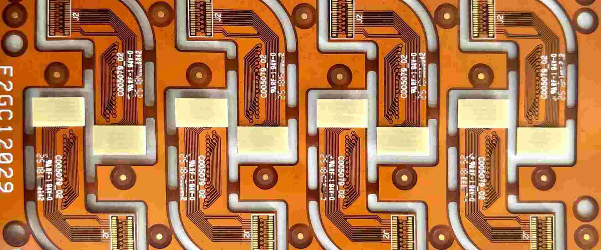
A flexible printed circuit board (flex PCB or flex circuit) is a type of printed circuit board that is made of flexible insulating material rather than the rigid material used for traditional PCBs. Flex circuits can be bent and flexed to fit mechanically challenging spaces and move dynamically within assembled products.
Flex PCBs are widely used in various electronics and devices where flexibility, space savings, or dynamic flexing is required. Some common applications include consumer electronics, medical devices, industrial equipment, aerospace systems, and automotive electronics.
One of the key design considerations for flex PCBs is determining the appropriate thickness for the application requirements. This article provides an in-depth look at the typical thickness ranges for flex circuits and the factors that influence thickness selection.
Typical Thickness Range

The thickness of a flex PCB refers to the height of the circuit after laminating the conductive copper traces between insulating flexible material layers.
Flex circuit thickness is commonly specified in imperial units of mils or inches. 1 mil = 0.001 inches.
Typical thickness values for flex PCBs range from:
- 1 mil (0.001″) – Used in extremely tight spaces requiring maximum flexibility. Mostly single layer circuits.
- 2 mils (0.002″) – Thinner standard flex circuits. May be single or double layer.
- 3 mils (0.003″) – Common thickness for double layer flex circuits. Provides good balance of flexibility and durability.
- 5 mils (0.005″) – Thicker flex circuits, more rigid than 3 mil. Used when more layers or stiffness is required.
- 7-10 mils (0.007″-0.010″) – Approaching the maximum for flex circuit thickness. Used in rigid-flex applications.
- 10+ mils (0.010″+) – Very thick flex circuits bordering on rigid-flex. Provides ruggedness needed in some applications.
Beyond 10 mils, the circuit is usually referred to as a rigid-flex PCB which contains both flexible and rigid PCB areas in a single circuit. Rigid-flex thickness can range up to 60 mils (0.060″) or more.
Factors that Determine Flex PCB Thickness
Several factors come into play when determining the ideal thickness for a particular flex PCB application:
1. Number of Conductive Layers
- The number of copper layers (conductors) required for the circuit layout has a direct impact on overall thickness.
- Single layer flex circuits can be extremely thin down to 1 mil.
- Two conductive layers require a minimum of about 2 mils.
- More than two layers will increase thickness further. Four to six layers are common.
2. Flexibility and Dynamic Bending Requirements
- For applications requiring tight dynamic flexing and repetitive motion, thinner flex materials down to 1 mil are used.
- If the circuit will only flex once during installation, a thicker 5+ mil circuit can be used.
3. Type of Insulating Material
- The dielectric material properties influence the minimum thickness for a given number of layers.
- Polyimide films like Kapton allow very thin 1-2 mil circuits.
- Other films like PET, PEN, PI require 2 mils or more for a double layer circuit.
4. Conductor Thickness
- Copper thickness is typically 1⁄2 oz (0.5 mil) or 1 oz (1 mil) per layer. Thicker copper increases minimum thickness.
5. Stiffness Requirements
- Some applications require the flex PCB to have enough stiffness for handling, connection, etc. This may dictate a 5 mil or thicker circuit.
- Added stiffeners can also increase thickness while maintaining flexibility in bend areas.
6. Component Spacing
- For dense fine pitch components, thinner materials down to 2 mils may be needed.
- Larger spacing and components allow room for thicker 5+ mil circuits.
7. Stackup Construction
- Adhesiveless constructions allow thinner flex as no bond films are present.
- Bonded constructions require adhesive films between layers that increase total thickness.
8. Protective Coatings
- Coverlayers, shielding, and stiffeners can add 1-3 mils for protection and durability.
Construction of a Flex PCB
A typical flex circuit consists of the following elements, from the top down:
- Cover Film/Masking: A thin polyimide or other protective layer that is added to the top and/or bottom for protection, identification, solder masking, etc. Optional, adds up to 3 mils thickness.
- Adhesive: Acrylic or epoxy adhesive used to bond multiple layers together if required. Adds approximately 1 mil per adhesive layer. Can be omitted in adhesiveless constructions.
- Conductor: Copper traces making up the circuit patterns. Standard 1⁄2 or 1 oz thickness per layer, approximately 0.5-1 mil.
- Base Insulator: Thin polyimide or other plastic film that forms the flexible substrate material. Available in thicknesses down to 0.5 mil and up depending on type.
- Adhesive: Used to bond base insulator and cover layers if required.
- Cover Film: Protective layer on bottom. Same as cover film on top side.
The minimum thickness of a 2 layer flex PCB would be the base insulator thickness + 2 times the copper thickness. For example, a 2 mil polyimide base with 1 oz (1 mil) copper on each side would have a total thickness of 2 mils (base) + 2 mils (2 copper layers) = 4 mils.
More layers would increase thickness further. The construction method (bonded, adhesiveless) also impacts overall thickness.
Typical Applications by Thickness
Below are some typical flex PCB applications organized by common thickness ranges:
1 mil Flex Circuits
Extremely thin 1 mil flex circuits are typically single layer and provide maximum flexibility for tight bending radiuses. Common applications:
- Wearable electronics
- Medical sensors
- Flex antennas
- Small consumer electronics
2 mil Flex Circuits
- Flex interconnects between PCBs
- Dynamic flexing cables
- Hinge connections
- Foldable circuits
- Medical devices
3 mil Flex Circuits
- Consumer electronics – cell phones, laptops
- Automotive sensors
- Industrial automation
- Aerospace and defense systems
5 mil Flex Circuits
- Consumer devices – larger circuits
- Automotive – dynamic engine cabling
- Industrial equipment
- Medical – instrument flex cables
7-10 mil Flex Circuits
- Rigid-flex combinations
- Military and aerospace systems – thick polyimide dielectric
- Automotive – thick flexible cabling
Flex PCB Thickness Tolerances
Because flex PCB thickness directly impacts the ability to fit and function in the intended application, tight tolerances are usually required.
General manufacturing tolerances on flex circuit thickness are:
- 1-2 mil thicknesses: ±10%
- 3-5 mil thicknesses: ±8%
- Above 5 mils: ±6%
For polyimide film materials like Kapton, thickness tolerance is ±5%. Tighter tolerances down to ±2% are possible with some flex circuit fabricators.
How Thickness is Measured
Flex circuit manufacturers use precision micrometers to measure thickness at multiple locations across a panel or individual circuit. Measurements are taken on fully cured circuits that have been laminated under heat and pressure.
Two types of micrometers are commonly used:
- Deadweight micrometers – Uses precisely machined parts and weighted probes to exert constant force. Very high accuracy (+/- 1%).
- Electronic micrometers – Uses electrical sensors to digitally measure thickness. Slightly less accuracy but faster measurement.
Thickness values are recorded and the standard deviation calculated to determine if the measurement is within the specified tolerance band. Out of tolerance conditions can be addressed by adjusting lamination parameters on subsequent panels.
Considerations for Thin Flex Circuits
While thin 1-2 mil flex circuits provide excellent flexibility in tight spaces, there are some design and manufacturing considerations to bear in mind:
- Thin circuits are inherently more fragile and prone to damage. Care must be taken in handling and assembly.
- They are also more susceptible to cuts and abrasion during dynamic flexing if not properly supported or guided.
- Traces and spaces must be designed larger as manufacturing tolerances are proportionally tighter on thinner circuits.
- Registration between layers can be more difficult to control below 2 mils requiring advanced fabrication processes.
- Thinner materials will take more care during component attach processes to avoid localized stress damage.
Rigid-Flex PCB Thickness
At the other end of the spectrum from thin 1 mil flex, rigid-flex PCBs occupy the 10 mil and greater thickness range. Rigid-flex combines both rigid FR-4 PCB laminates and flexible circuit materials into a single integrated assembly.
Rigid board thickness in rigid-flex circuits typically ranges from:
- 20 mil – 0.020″ – Typical rigid PCB thickness
- 30 mil – 0.030″ – Medium thickness for good stiffness
- 60 mil – 0.060″ – Very thick, approaching maximum rigid board thickness
The rigid sections are then interconnected by thinner flexible circuits ranging from 2 to 8 mils to allow dynamic folding and shape conforming capabilities.
An example rigid-flex construction may consist of:
- 0.060″ thick rigid PCB sections
- 5 mil polyimide flex interconnects
- Total thickness around 0.065″
In this manner rigid-flex PCBs can provide both the density and durability of rigid boards along with flexible circuits in one package. The combination of thin flex and thick rigid areas leads to an overall thickness that can exceed 10 mils or more.
Summary
To summarize, flex PCB thickness typically ranges from:
- 1 mil (0.001″) – Single layer dynamic flexing
- 2 mils (0.002″) – Double layer tighter flex circuits
- 3 mils (0.003″) – Standard thickness for most flex applications
- 5 mils (0.005″) – Thicker more rugged flex circuits
- 7-10 mils (0.007″-0.010″) – Approaching rigid-flex territory
Many factors determine the optimal thickness including number of layers, flexibility requirements, dielectric material, conductor thickness, and construction method among others.
Understanding both the design needs and manufacturing capabilities will lead to selecting the right flex circuit thickness for the application. Rigid-flex PCBs allow combination of multiple thicknesses in a single assembly spanning up to 60 mils or more. Careful measurement and tight tolerances help ensure the circuit meets the demanding fit and performance requirements.
Frequently Asked Questions
What is the most common thickness for a flex PCB?
The most common standard thickness for flex PCBs is around 2-3 mils. This provides a robust circuit thickness for the majority of flex PCB applications while still allowing good flexibility and bend radius.
How thick can flex PCBs be made?
The maximum thickness for pure flex circuits is typically 8-10 mils. Beyond this thickness, rigid-flex PCB technology is used which can allow total thicknesses exceeding 60 mils by combining rigid board and flex circuit technologies.
Why are flex PCBs made so thin?
The main advantages of thin flex PCBs in the 1-3 mil range are the ability to dynamically flex and conform to tight spaces that would be impossible with rigid boards. Thinner flex PCBs can fold into very tight radii and fit into extremely thin assemblies.
What determines the minimum thickness of a flex PCB?
The minimum achievable thickness is largely driven by the number of conductive copper layers and properties of the base insulating material. Simple single layer construction with polyimide film can reach 1 mil. Two copper layers require at least 2 mils with typical polyimide films.
How accurate are flex PCB thickness measurements?
Precision micrometers allow thickness measurements and tolerances within ±5% or better for most flex circuit fabricators. Tighter tolerances are possible but may require advanced processes to control material and lamination factors.


Leave a Reply