Introduction to flex rigid PCBs
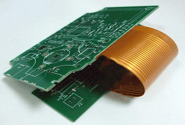
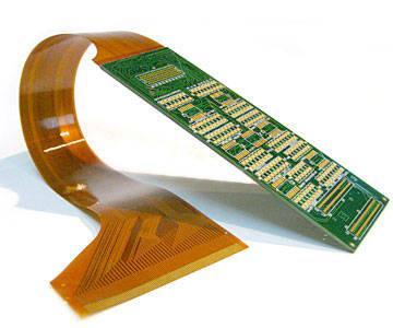
A flex rigid PCB, also known as a rigid flex PCB or flex-rigid PCB, is a printed circuit board that consists of flexible and rigid substrates laminated together. This allows the PCB to bend and flex in certain areas while maintaining rigidity in others.
Flex rigid PCBs provide several advantages over standard rigid PCBs:
Flexibility and Movement
The flexing regions of the PCB allow movement and adjustments between the rigid sections. This helps:
- Accommodate different contours and space requirements
- Absorb stresses from motion and vibration
- Allow components to be placed on moving or articulating sections
Reliability
The solid foundation provided by the rigid sections helps prevent crack propagation into solder joints and traces, improving reliability.
Weight and Space Savings
By folding and contouring, flex rigid PCBs can fit into tight spaces and small form factors, saving weight and space.
Design Freedom
The combination of rigid and flex allows for more creative and innovative PCB solutions that would not be possible with rigid technology alone.’
Typical Construction of Flex Rigid PCBs
Flex rigid PCBs can have many configurations, but typically consist of:
- Rigid laminate substrates (usually FR-4)
- Flexible laminate substrates (usually polyimide)
- Adhesive layers (bonding films)
The rigid and flex sections are precisely aligned and laminated together under heat and pressure to form a single integrated PCB unit.
The rigid sections provide mechanical support while the thin flex layers allow dynamic movement as needed.
Popular Uses of Flex Rigid PCBs
Due to their unique combination of flexibility and rigidity, flex rigid PCBs are used in a wide variety of applications, including:
Consumer Electronics
- Cell phones
- Laptops
- Digital cameras
- Wearable devices
Industrial
- Robotics
- Automation equipment
- Factory testing fixtures
Medical
- Hearing aids
- Patient monitors
- Imaging equipment
Military/Aerospace
- Guidance systems
- UAVs and drones
- Avionics
Automotive
- Navigation and infotainment displays
- Onboard computer systems
- Sensors
Almost any application that requires a complex, space-constrained circuit board with flexible aspects can benefit from flex rigid PCB technology.
Flex Rigid PCB Design Considerations
Designing a flex rigid PCB requires special considerations, both in the mechanical and electrical realms.
Mechanical
- Bend zones – The flexible areas of the PCB must be carefully layout out and use properly tested flexible laminates. These bend zones allow the PCB to fold and contour.
- Stiffeners – Rigid support structures may need to be incorporated to bolster the flexing regions against tearing and crack propagation.
- Adhesives – The bond between the rigid and flex layers is crucial. High performance adhesive films are specially formulated to join different materials while allowing flexing without delamination.
- Layer stackup – Determining the order and precise alignment of the layers during lamination is an essential aspect of flex-rigid design.
- Stresses – The stresses and lifecycle flexing parameters must be analyzed to ensure reliable functionality and avoid early breakage.
Electrical
- Routing – Traces must be properly routed from the rigid sections, through the bend zones, and back to the rigid sections. Controlled impedance traces may require special compensation features.
- Components – Only specially tested flexible components should be used on the flexing portions of the PCB.
- Testing – Thorough testing should be conducted in both static and dynamic flexed states to ensure electrical performance.
- Shielding – Since the board flexes, traditional shielding methods may not work, requiring specialized EMI/RFI shielding techniques.
Careful consideration of these factors early in the design process is highly recommended when implementing a flex rigid PCB.
Flex Rigid PCB Fabrication Process Overview
The fabrication of flex rigid PCBs requires specialized processes and equipment. Here is a general overview:
Step 1 – Circuit Design
The circuit connectivity, layer stackup, component placement, routing, and bend zones are designed using specialized rigid flex CAD tools.
Step 2 – Prototyping
Initial prototypes are typically built using the same processes as final production. This verifies the intended flexibility, fit, and electrical functionality before full production occurs.
Step 3 – Imaging
The rigid and flex layers are imaged with photoresist to transfer the circuit traces pattern onto the laminate cores. This is similar to standard rigid PCB fabrication.
Step 4 – Etching and Processing
The boards go through etching, hole drilling, and other circuit patterning processes to achieve the intended connectivity.
Step 5 – Lamination
The separate rigid and flex layers are precisely aligned and laminated together under high heat and pressure using adhesive films. This permanently bonds the layers into an integrated flex rigid board.
Step 6 – Final Testing
Once the basic board is assembled, components are soldered on and the fully populated board is electrically and mechanically tested. Testing is performed in both rigid and flexed states.
By utilizing advanced materials and processes, PCB fabricators can produce highly reliable flex rigid boards that function consistently through years of use.
Benefits of Using Flex Rigid PCBs
Here is a summary of the major benefits that flex rigid PCB technology provides:
| Benefit | Description |
|---|---|
| Smaller Size | Folds into 3D shapes for tighter space savings |
| Lower Weight | Thinner than rigid boards due to flexible layers |
| Increased Reliability | Flex areas absorb motions preventing cracking |
| Lower Assembled Cost | More compact form reduces overall system expense |
| Design Flexibility | Bend areas offer more creative layout options |
| Improved Serviceability | Components can be placed for easier access |
| Shielding Ability | Built-in EMI shielding with rigid sections |
For electronic devices and systems that need complex, movable, or compact circuit boards, flex rigid PCBs deliver substantial advantages over rigid boards.
Flex Rigid PCB Cost Factors
Flex rigid PCBs provide many benefits, but generally have higher fabrication costs compared to standard rigid PCBs. Some of the main factors affecting flex rigid pricing include:
- Layer count – More layers means more materials and processing, increasing costs.
- Board size – Larger boards use more base materials.
- High density designs – Many traces, holes, and fine features require additional steps.
- Special materials – Advanced flex laminates and adhesives can increase expenses.
- Certifications – Rigorous testing/approvals like ISO 9001 lead to higher costs.
- Location – Where the PCBs are built affects labor/import costs.
- Order volume – Lower quantities have less economy of scale savings.
- Rush orders – Faster delivery times often increase charges.
However, the enhanced performance from flex rigids frequently justifies the price premium in applicable products. And costs can be managed by minimizing unnecessary requirements.
Outlook for Flex Rigid PCB Technology
The global market for flex rigid PCBs was over $10 billion in 2022, and will continue experiencing strong growth this decade as electronics manufacturers take advantage of their capabilities and constantly shrinking form factors.
Here are some key trends influencing the accelerated adoption of flex rigid PCB technology:
- 5G Devices – Next generation wireless infrastructure and multifunction mobile products utilize flex rigids extensively due to intense space and performance demands.
- Electric Vehicles – Flexible/rigid combinations allow for lighter circuit boards that withstand automotive vibration forces and impacts.
- Smart Devices – The Internet of Things and embedded intelligence relies on small interconnections between sensors, processing, and actuators enabled by flex-to-rigid constructions.
- High Speed Digital – Advancements in flex material dielectric properties supports ultra high speed signaling across bends.
- Medical Electronics – Shrinking medical instruments like endoscopes and therapies embed computing on closely conformed flex rigid boards.
As electronics innovation continues progressing, flex rigid PCBs will be at the forefront of enabling many new products with their unique blend of characteristics.
Flex Rigid PCB Frequently Asked Questions
Here are answers to some common questions about flex rigid PCB technology:
What are the main differences when comparing rigid flex PCB vs rigid PCB?
The primary differences are:
- Rigid flex PCBs have flexible substrate areas, rigid PCBs do not bend
- Layer stackups and laminations differ between construction methods
- Rigid flex requires specialized design rules and fabrication processes
- Flexible portions provide ability to contour and dynamically adjust
- Overall reliability improves in high vibration environments
Can components be soldered onto the flexing areas of a rigid flex board?
Yes, but the components used must be specifically flexibility graded by the manufacturer to withstand the stresses without lead breakage or other issues. Not all standard surface mount components are suitable for deforming PCB sections.
What are some examples of rigid flex PCB applications?
Some common product examples using rigid flex PCB technology include cell phones, laptops, robots, aerospace avionics, medical instruments like endoscopes, and advanced industrial equipment with dynamic movements or tight space constraints. The automotive market also uses rigid flex to reduce weight and improve electronics reliability.
How long is the typical lifespan of a rigid flex PCB?
With robust design and manufacturing methods, rigid flex PCBs can have lifespans exceeding 10 years and over 10,000 dynamic bend cycles. Product life is highly dependent on the quality processes used such as stress analysis, bend radius control, adhesive selection, and electrical/mechanical testing.
Can traditional FR-4 substrates be used instead of polyimide in the flexible areas when making rigid flex PCBs?
No, standard FR-4 laminates lack the required flexibility, heat resistance, and dimensional stability attributes for dynamic bending applications. They are too brittle and will crack when folded repeatedly. Polyimide films or other specialty flex laminate materials must be used in the hinge areas of rigid flex constructions.
Conclusion
With their ability to integrate rigid board sturdiness and connectivity with flexible contours and motion, flex rigid PCBs empower electronic product designers to shrink form factors, improve reliability, and embed computing intelligence in novel packages. As new 3D packaging and embedded computing trends drive PCB complexity, flex rigid technology will play an increasingly pivotal role due to its special capabilities. Engineers across nearly every industry are adopting flex-rigid solutions for next generation products with small, high performance, and reliable circuitry. With skilled design and fabrication expertise applied, rigid flex PCBs deliver substantial benefits across an ever wider range of demanding applications.


Leave a Reply