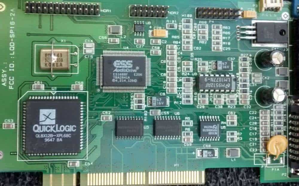
A printed circuit board (PCB) transformer is a type of transformer that is manufactured directly onto a printed circuit board (PCB). PCB transformers provide galvanic isolation and allow signals and power to be transformed and transferred between circuits.
How PCB Transformers Work
PCB transformers work on the same principles as traditional wire-wound transformers. They consist of two or more coils of copper traces printed directly onto a PCB. The coils are placed close together but do not physically touch, allowing electromagnetic induction between the windings.
When an AC voltage is applied across one coil, called the primary winding, it generates a magnetic flux in the transformer’s core. This changing magnetic flux induces a voltage across the second coil, called the secondary winding. By stepping up or down the number of turns in each coil, small voltages can be transformed to high voltages and vice versa.
PCB Transformer Design
PCB transformers allow for much greater design flexibility compared to old fashioned wire wound types. Factors in PCB transformer design include:
- Number of coil turns
- Coil area
- Distance between windings
- Type of core material
- Size and shape of core
- PCB copper thickness
- Frequency
Engineers can optimize these parameters through simulation and modeling to achieve the voltage transformation ratio, efficiency, and performance characteristics required.
PCB fabrication allows transformers to be designed in a huge variety of shapes and configurations to suit the application. Multiple windings or taps can be implemented far more easily compared to manually winding wires.
Types of PCB Transformers
There are two main types of PCB transformer based on the core material: air core and magnetic core.
Air Core Transformers
Air core PCB transformers have no magnetic core material. The transformer coils are printed on the PCB with just air between them
Without a magnetic core, air core transformers have low inductance and poor coupling between windings. However, they provide galvanic isolation and work well at high frequencies above 1MHz. Air cores have higher leakage inductance and are more prone to electromagnetic interference (EMI).
Common applications for air core PCB transformers include impedance matching, balanced-unbalanced conversion, and safety isolation.
Magnetic Core Transformers
Magnetic core PCB transformers use a ferromagnetic core between coils to increase magnetic coupling. Common core materials include ferrites and iron powders:<div align=”center”>
| Core Material | Properties |
|---|---|
| Ferrite | High resistivity, used for signal & SMPS transformers up to 5 MHz |
| Iron Powder | Low resistivity, used for power transformers up to 500 KHz |
Magnetic cores greatly improve energy transfer between windings compared to air cores. This allows PCB transformers with magnetic cores to achieve much higher inductance values. They provide moderate isolation and work well in the frequency range of 10 KHz up to 5 MHz.
Applications include DC-DC converters, gate drive transformers, and isolation in switch mode power supplies.

PCB Transformer Manufacturing
PCB transformers are manufactured using the same equipment and processes as regular printed circuit boards. The following steps are involved:
- Design – The transformer is designed in CAD software. Critical parameters like copper fill, trace spacing and core geometry are modeled and simulated.
- Etching – Boards are etched to create the windings, taps and connections. Modern PCBs use a chemical process while older boards were rubylith masked.
- Core Assembly – Cores are assembled between windings. This may involve hand gluing or robotic automation.
- Testing – Each PCB transformer is electrically tested before shipment. Automated test fixtures apply voltage and measure inductance, resistance and breakdown voltages.
The same SMT assembly processes are used to mount PCB transformers as for other surface mount components. For large power transformers, additional mounting points or brackets may be required.
Applications of PCB Transformers
The flexibility of PCB transformer construction allows application across a vast range of areas:<div align=”center”>
| Application | Uses |
|---|---|
| Switch Mode Power Supplies | Isolation, voltage transformation |
| Gate Drive Circuits | Fast voltage shifting |
| USB & Data interfaces | Signal coupling, ESD protection |
| Audio Amplifiers | Impedance matching |
| High Voltage Circuits | Generate kV voltages for tubes or igniters |
| Electric Vehicles | Power inverters, onboard charging |
| Power Over Ethernet | Voltage regulation |
Benefits of using PCB transformers include:
- One-piece construction
- Ease of automation
- Flexible form factors to suit circuit needs
- Integrates well with surface mount assembly
- Lower costs in medium to high volumes
For these reasons, demand for PCB transformers is forecast to grow rapidly as a replacement for wire wound types.
Design Considerations
Engineers need to evaluate the following design factors when specifying PCB transformers:
Power Level
The power level impacts all aspects of the transformer design from trace sizes to clearances to core material selection. A transformer that handles 50W will be very different to one for 0.5W. Cooling may also need consideration.
Inductance Value
The inductance of PCB windings is generally small, so magnetic cores are necessary for values about 10μH. The core material, size, type (closed or open), and configuration directly impact achievable inductance.
Voltage Isolation
The breakdown voltage will be determined by PCB trace spacing and core insulation properties. Many kilovolts can be accommodated with the right design. Safety standards also dictate minimum creepage distances.
Frequency Range
The operating frequency influences core loss characteristics and winding capacitances. High frequencies favor air core or ferrite designs while powdered iron works better for low frequencies.
Cost
PCB transformers lend themselves to high volume automated production. While small batch prototyping will still be costly, prices drop dramatically at mid to large production runs.
Optimizing all the above factors results in the most compact, efficient and cost-effective PCB transformer design.
Comparison to Wire-Wound Transformers
PCB transformers offer several advantages over old fashioned wire wound types:<div align=”center”>
| Parameter | PCB Transformer | Wire Transformer |
|---|---|---|
| Construction | Automated PCB processes | Manual winding and assembly |
| Repeatability | Excellent | Moderate |
| Size vs Power | Very compact | Larger |
| Shape Flexibility | Any 2D geometry | Limited by manual winding |
| Cost (mid-high volumes) | Lower | Higher |
The main disadvantage of PCB transformers is higher unit costs at very low volumes. However, the ability to integrate transformers directly into the PCB with automated production delivers substantial savings, size and reliability benefits as quantities increase.
Frequently Asked Questions
Here are some common questions about PCB transformers:
Can you create a non-standard shaped transformer on a PCB?
Definitely. One of the biggest advantages of PCB transformers is the design freedom to create all sorts of innovative winding layouts and core shapes to meet specialized needs. Non-standard shapes like circles, diagonals, slots and holes can be readily etched onto the PCB copper layers to form the transformer windings.
Does placing other components near the transformer cause issues?
Placing other PCB components too close to the transformer can negatively impact performance in some cases. The magnetic fields can induce eddy currents and losses in nearby conductive materials. Critical circuit nodes may also couple in unwanted noise.
However, with good PCB layout it is generally fine to position passive components like resistors and capacitors very close. Proper grounding and spacing of sensitive active components is advisable though. Simulation helps identify any design trouble spots.
Can multiple windings be created on one PCB?
Definitely. A key benefit of PCB transformers is that multiple isolated windings can be printed on the same board very easily. 2, 3 or even 4 separate coils are straightforward to integrate together with different turn ratios. Producing such a transformer with hand wound wires would be very manual intensive and bulky.
Does PCB board thickness matter for transformers?
Yes it can make quite a difference. Thicker copper PCBs reduce resistive losses in the windings, allowing more power handling for a given footprint. 1oz, 2oz and 3oz boards are common. IMPORTANT: Ask PCB manufacturer for copper WEIGHT (not thickness) when specifying boards.
Is it possible to directly solder wires to PCB transformer windings?
Absolutely. PCB windings can be designed with solder pads or through-hole eyelets to facilitate simple terminations. For boards with tighter space requirements, surface mount pads work well too. So electrical connections to other PCBs or external wires can be readily incorporated.


Leave a Reply